
Massoth reverse loop module 8157001. How can I test it out of the layout?

railaddict

Registered
Country flag
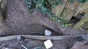
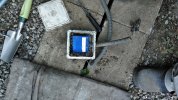
I have removed from the ground my reverse loop module. It has been buried for the last 12 years and worked ok until the last time I used it but that was before the problems on the track.
I would like to know if there is a possibility to test the module but I cannot connect it to the layout because it is not possible for the moment to connect anything the whole layout being rebuilt.
IMG_20260925_165553.jpgIMG_20260925_183214_6.jpgIMG_20260929_121142.jpg

In the meantime, I’ve sprayed on some WD-40 Specialist quick-drying contact cleaner.

It’s not urgent, but if the module stops working, I can always buy another one if necessary.
 
I guess that if you put DCC into the input, you should be able to measure an AC voltage out.

You won't be able to check the polarity, but on the premise that there is an AC reading, rather than nothing, then the module hasn't failed totally....
 
PLEASE DON'T DO THIS UNTIL SOMEBODY ELSE CONFIRMS IF IT IS RIGHT.... but as the module works (in one of its modes) by sensing a momentary short as the loco wheels cross the return loop break, is it possible just to temporarily wire it up and then cause a momentary short, just to see if the module's relay(s) click...?

Have you been using it in "short-circuit mode", or using the sensor track pieces?

Jon.
 
I would like to know if there is a possibility to test the module

The module is triggered by a wheel closing the isolating gap between rail sections. The result of the trigger is the polarity of one if the track sections being inverted (in respect to the other track section) on one side of the isolating gap. You just need to replicate the trigger, while measuring the polarity of the feed on the isolated track section.
 
Last edited:
The module is triggered by a wheel closing the isolating gap between rail sections. The result of the trigger is the polarity of one if the track sections being inverted (in respect to the other track section) on one side of the isolating gap. You just need to replicate the tigger, while measuring the polarity of the feed on the isolated track section.

I think that's pretty much what I was trying to say above, but you've put it much more succinctly and technically!

Try not to replicate the Tigger though, or you'll be inundated by the annoying bouncy black-and-orange things... :D

Jon.
 
I have removed from the ground my reverse loop module. It has been buried for the last 12 years and worked ok until the last time I used it but that was before the problems on the track.
I would like to know if there is a possibility to test the module but I cannot connect it to the layout because it is not possible for the moment to connect anything the whole layout being rebuilt.
View attachment 361671View attachment 361672View attachment 361673

In the meantime, I’ve sprayed on some WD-40 Specialist quick-drying contact cleaner.

It’s not urgent, but if the module stops working, I can always buy another one if necessary.
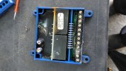
Not being electronically minded, but, unless I'm missing something, there's definitely something burnt out in that picture
 
Not being electronically minded, but, unless I'm missing something, there's definitely something burnt out in that picture
They are the jumpers for configuration, which appear to have corroded. - This may stop it working?

If it has been damp and powered, then tracks on the pcb may no longer be present, as well.

PhilP.
 
If you have enough track you could set up a test wye like I did here. Though this was an LGB one simikar setup would work for a Massoth one or possibly not if it is trashed.

 
PLEASE DON'T DO THIS UNTIL SOMEBODY ELSE CONFIRMS IF IT IS RIGHT.... but as the module works (in one of its modes) by sensing a momentary short as the loco wheels cross the return loop break, is it possible just to temporarily wire it up and then cause a momentary short, just to see if the module's relay(s) click...?

Have you been using it in "short-circuit mode", or using the sensor track pieces?

Jon.
The module is triggered by a wheel closing the isolating gap between rail sections. The result of the trigger is the polarity of one if the track sections being inverted (in respect to the other track section) on one side of the isolating gap. You just need to replicate the trigger, while measuring the polarity of the feed on the isolated track section.
They are the jumpers for configuration, which appear to have corroded. - This may stop it working?

If it has been damp and powered, then tracks on the pcb may no longer be present, as well.

PhilP.
If you have enough track you could set up a test wye like I did here. Though this was an LGB one simikar setup would work for a Massoth one or possibly not if it is trashed.

I think Jon's advice is the one I'll follow. I'm not sure I have enough spare track but being in the process of rebuilding the layout, I can borrow a point and track from the layout to reproduce the situation.
As I’ve been posting on the forum, I’ve come to realise that there’s more wisdom in two heads (or more) than in one. Thank you all for your views.
 
Back
Top Bottom