Massoth Reverse Loop Modules

duncan1_9_8_4

Jack of all trades on the Railway
25 Oct 2009
3,316
508
40
Pontefract, West Yorkshire
Best answers
0
Country flag
Afternoon....

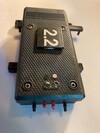
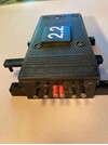
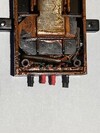
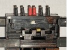
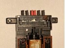
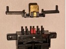
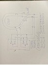
I have 3 Massoth Reverse Loop Modules that have worked fine for years. Gradually, one of them has started playing up. When a train passes over the Insulating Joints, it pauses then continues as it should. But it never used to pause the train. It's as if the module is not making the switch over quickly enough. I have uninstalled it and reinstalled it as if it was new, the problem persists. I have moved it to another Reverse Loop and it transfers the fault. I have moved a good one from elsewhere and all is fine. Indicateing it's something to do with the actual module.

Whilst I don't mind buying a new, is there a reason this might have happened and why?

The module was/is dry in a sealed box, and was fine until about 2 weeks ago.

Am I just unlucky and it's simply broken?

Any ideas welcome.

Thanks
 

Gizzy

A gentleman, a scholar, and a railway modeller....
26 Oct 2009
36,167
2,283
63
Cambridgeshire
www.gscalecentral.net
Best answers
0
Country flag
I believe that there is a small pcb mounted relay inside these modules (and the similar LGB one).

From my experience as an Electronics Engineer this relay will eventually start to wear out and act intermittantly.

I've changed pcb with these relays several times on other equipment, but never actually replaced a relay itself, although this is possible if you can identify and source a replacement. You would also have to be confident enough to open up your module and competent to solder a new relay. I don't think these modules come apart easily as they are effectively a 'sealed for life' item....
 
  • Like
Reactions: 1 user

PhilP

G Scale, 7/8th's, Electronics
5 Jun 2013
33,627
3,532
Nottingham
Best answers
0
Country flag
Last summers record-breaking heat (here in the UK) will have stressed much 'outdoor' electronics..
Electrolytic capacitors will have dried-out. Expansion may have cracked soldered joints, even pcb tracks. Components will probably have been working above their design limits?

Bringing things out of winter hibernation, will tend to be the time these things come to light. - Or more probably, 'dark'.?
:nerd::D

PhilP
 

Slawman

Deckline
9 Apr 2018
323
83
Sydney
Best answers
0
Country flag
I have moved from the Massoth units to this one:

Gaugemaster GM-DCC40 Prodigy​

So far so good. Seems a lot simpler and no short.
 

NG Retired

Registered
21 May 2023
11
1
74
England
Best answers
0
Country flag
Hi,
I've just had a similar problem, Massoth reverse loop failed. Spent too much time trying to identify where the problem actually lay.
In the end bought a new unit from P&S Hobbies and model, Back up and running within a couple of hours after receiving the replacement,
Good luck trying to solve your problem
 

Slawman

Deckline
9 Apr 2018
323
83
Sydney
Best answers
0
Country flag
I think the Massoth/LGB have relays, perhaps the Gaugemaster are solid state?

I am not sure of the workings. The Gaugemaster documentation is very brief. It talks about synchronising track polarity. The wiring for the Massoth in the "non shorting" implementation is a lot more complicated involving four track breaks each side of the loop you have to wire up. If both achieve the same then the Gaugemaster is superior in my opinion although since I am not really across the technologies I may well be missing something.....
 
8 Mar 2014
7,806
972
San Diego
Country
Armenia
www.elmassian.com
Best answers
0
Country flag
I was talking about relays, because they are a mechanical item and can be a source of failures.

The Gaugemaster changes polarities only by detecting a short, like what is overwhelmingly used in the USA by all scales.

The Massoth/LGB works on DC and DCC and can do both short detection or use the "trigger sections". Running on DC usually forces the system to use relays, for electronic design reasons.

Greg
 

Slawman

Deckline
9 Apr 2018
323
83
Sydney
Best answers
0
Country flag
I was talking about relays, because they are a mechanical item and can be a source of failures.

The Gaugemaster changes polarities only by detecting a short, like what is overwhelmingly used in the USA by all scales.

The Massoth/LGB works on DC and DCC and can do both short detection or use the "trigger sections". Running on DC usually forces the system to use relays, for electronic design reasons.

Greg
What is the point/benefit of the added complexity of the Massoth unit?
 
8 Mar 2014
7,806
972
San Diego
Country
Armenia
www.elmassian.com
Best answers
0
Country flag
Well, the first and most obvious advantage is the ability to work on DC. Most Autoreversers are DCC only.

The next is a point of opinion. There is a group of people who abhor the "short circuit sense" mode of operation on DCC, fearing excessive pitting of wheels, or some other reason.

Thousands of hours have proven this concern unfounded, but for those who feel that way on DCC, then the sensor operation is for them. That's the "pro's"

The added complexity and cost is chief of the "con's" for the Massoth.

Greg
 
Last edited:

Gerard

Registered
26 Mar 2021
126
16
74
Aerdenhout Holland
Best answers
0
Country flag
I like to share my latest experience with a new switch relais design made by a friend of me who is for more than 40 year selling/repairing/improving/using LGB trains. For several years i was using the relais solution for the reverse loop using a LGB switch motor with a Zymo MX 820 D decoder. Using this decoder the switch could be handled by the dcc system. This decoder also provides the use of two rail contacts, both to be placed at each end of the loop close to the switch.
Activating one railcontact bij de first (steel) wheel of the train when leaving the loop makes the switch to be set in the direction of that train and at the same time the switch of the polarity of the loop to the rails behind the switch in front of the train. For switching the polarity, untill recently, i used the supplementary switch T2 (LGB 12070) that must be connected with a "click" connection to the end of the switch motor. However, on the long run in a year around operational garden rail this click connection is not enough sturdy connected to the switch motor and sealed against "wind and wheater and little creatures" thus causing connection problems on the long run.
A friend of my redesigned the LGB switch at both ends. At the one end by removing the AC connector points with the two screws and replacing them by a flat printplate inside with 4 small single wire connectors (2 red and 2 black) soldered perpendicular on this printplate and coming out the black box via 4 small holes.( See pictures 1and 3) . By doing so he also created a lot more space to put in the decoder. At the other end of the black box he build in two switch contacts, each having two connectors (black), and in the middle two contact points (red) to feed the the loop. (See pictures 2 and 4-7)The result is a switch motorblock with no open screw holes on top any more. See attached photos. For convenieance i added picture 8 showing the switch relais connections. His price for building in this relais (his code RBK 310610) for 29 euro , together with the decoder of 35 euro the total price for this conversion is 64 euro.
If anybody is interested than mail me your mail address and i will send you his mailaddress.
 

Attachments

  • 1  contact points 2 red for feed from rails and 2 black for two railcontacts.jpg
    1 contact points 2 red for feed from rails and 2 black for two railcontacts.jpg
    18.1 KB · Views: 0
  • 2 contact points for 6 relais connections.jpg
    2 contact points for 6 relais connections.jpg
    15.1 KB · Views: 0
  • 3 inside look at decoder.jpg
    3 inside look at decoder.jpg
    21 KB · Views: 0
  • 4 inside look relais switches and switch handle.jpg
    4 inside look relais switches and switch handle.jpg
    24.5 KB · Views: 0
  • 5 inside look relais after removing switch handle.jpg
    5 inside look relais after removing switch handle.jpg
    19.5 KB · Views: 0
  • 6 separate switch handle top view.jpg
    6 separate switch handle top view.jpg
    18.1 KB · Views: 0
  • 7 separate switch handle side view.jpg
    7 separate switch handle side view.jpg
    17 KB · Views: 0
  • 8 Relais scheme for a reverse loop.jpg
    8 Relais scheme for a reverse loop.jpg
    45.6 KB · Views: 0

duncan1_9_8_4

Jack of all trades on the Railway
25 Oct 2009
3,316
508
40
Pontefract, West Yorkshire
Best answers
0
Country flag
What might make a Reverse Loop module start clicking intermittently even when not in use. Seems to happen occasionally when a train in in a certain incline
 

dunnyrail

DOGS, Garden Railways, Steam Trains, Jive Dancing,
Staff member
GSC Moderator
25 Oct 2009
26,225
5,000
75
St.Neots Cambridgeshire UK
Best answers
0
Country flag
Without doubt the safest solution if you can manage it is to have the module in a dry shed, running out the wires to where they are needed. We have done this on a friends line and the module is still working no problems after 14 or so years.
 

duncan1_9_8_4

Jack of all trades on the Railway
25 Oct 2009
3,316
508
40
Pontefract, West Yorkshire
Best answers
0
Country flag
Without doubt the safest solution if you can manage it is to have the module in a dry shed, running out the wires to where they are needed. We have done this on a friends line and the module is still working no problems after 14 or so years.
I presume they are reliant on a steady and constant power supply too?