collectors
Registered
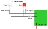
Hi, wanted to fit a Bi-led to front & rear "Red/White" for direction lights on terminals P1 & P2 & wasn't sure if i should be buying Common Anode or Cathode. Or have i got this part wrong ??
Are the P1 and P2 on a Deltang or Micron receiver or on something else?Hi, wanted to fit a Bi-led to front & rear "Red/White" for direction lights on terminals P1 & P2 & wasn't sure if i should be buying Common Anode or Cathode. Or have i got this part wrong ??
What I was thinking..Are the P1 and P2 on a Deltang or Micron receiver or on something else?
Rik
 I would have posted a link to the LED wiring information there..
Sorry, yes a Deltang or the new Micron receiver. I have both.Are the P1 and P2 on a Deltang or Micron receiver or on something else?
Rik
Either set of instructions will give you the information..Sorry, yes a Deltang or the new Micron receiver. I have both.
Hi Phil. with using the 2 wire led, am i right in that P1 & P2 change polarity when the train is changing direction to get the led to go from red to white. ??Either set of instructions will give you the information..
Pads 1&2 give 3.5V when 'on' and so you connect (with resistor) from the pad to battery negative.
You may find that you can get two-lead, bi-colour LEDs more easily?
You can connect these between Pads 1&2, don't forget a resistor, but are limited to two LEDs due to current limits of these outputs.
The 'A' & 'B' outputs, can give you a lot more current capacity, but switch to 0V when 'on'.
So you connect to the battery positive. Again, don't forget the resistor.
PhilP.
I use two wire twin colour LED for lights, however I attach them (with the appropriate resistor) to the motor connectors, so applying power, even before the loco moves the lights come onHi Phil. with using the 2 wire led, am i right in that P1 & P2 change polarity when the train is changing direction to get the led to go from red to white. ??
")
That is correct..Hi Phil. with using the 2 wire led, am i right in that P1 & P2 change polarity when the train is changing direction to get the led to go from red to white. ??
I changed the previous image. Any better ??No.
You wire the LEDs (and resistor) between Pins 1&2..
Pins 1&2, are 3.5V when 'on' and 0V when 'off', so when you change direction the polarity of the voltage between Pins 1&2 changes.
PhilP
It still looks incorrect to me, just connect to P 1 and 2 - short leg from one and long leg from the other on P1 and opposite for P2I changed the previous image. Any better ??
Looks good to me.PS: have changed the image again.
I was going to say, it looks ok to me, so why is Phil saying "No"I changed the previous image. Any better ??
 ...... Then I read further.....
 Hi PhilYou got it.
What did you use to draw your diagram?
I am still looking for something to do mine..
PhilP
Its actually a WYSIWYG web page/site builder that i used to build many websites but moved on to WIX now as its free. The website builder is also free. Go to this page & download If you need any help let us know.,You got it.
What did you use to draw your diagram?
I am still looking for something to do mine..
PhilP