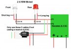
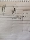
Hi, wanted to fit a Bi-led to front & rear "Red/White" for direction lights on terminals P1 & P2 & wasn't sure if i should be buying Common Anode or Cathode. Or have i got this part wrong ??
Bi led, Common Anode or Cathode
- Thread starter collectors
- Start date
You are using an out of date browser. It may not display this or other websites correctly.
You should upgrade or use an alternative browser.
You should upgrade or use an alternative browser.
Are the P1 and P2 on a Deltang or Micron receiver or on something else?Hi, wanted to fit a Bi-led to front & rear "Red/White" for direction lights on terminals P1 & P2 & wasn't sure if i should be buying Common Anode or Cathode. Or have i got this part wrong ??
Rik
What I was thinking..Are the P1 and P2 on a Deltang or Micron receiver or on something else?
Rik
IF I could have got into the website
PhilP
Sorry, yes a Deltang or the new Micron receiver. I have both.Are the P1 and P2 on a Deltang or Micron receiver or on something else?
Rik
Either set of instructions will give you the information..Sorry, yes a Deltang or the new Micron receiver. I have both.
Pads 1&2 give 3.5V when 'on' and so you connect (with resistor) from the pad to battery negative.
You may find that you can get two-lead, bi-colour LEDs more easily?
You can connect these between Pads 1&2, don't forget a resistor, but are limited to two LEDs due to current limits of these outputs.
The 'A' & 'B' outputs, can give you a lot more current capacity, but switch to 0V when 'on'.
So you connect to the battery positive. Again, don't forget the resistor.
<Edit> You can not use these outputs for two-wire bi-colour LEDs. - When they are 'off' they are 'open-circuit', so no connection.
PhilP.
Last edited:
Hi Phil. with using the 2 wire led, am i right in that P1 & P2 change polarity when the train is changing direction to get the led to go from red to white. ??Either set of instructions will give you the information..
Pads 1&2 give 3.5V when 'on' and so you connect (with resistor) from the pad to battery negative.
You may find that you can get two-lead, bi-colour LEDs more easily?
You can connect these between Pads 1&2, don't forget a resistor, but are limited to two LEDs due to current limits of these outputs.
The 'A' & 'B' outputs, can give you a lot more current capacity, but switch to 0V when 'on'.
So you connect to the battery positive. Again, don't forget the resistor.
PhilP.
I use two wire twin colour LED for lights, however I attach them (with the appropriate resistor) to the motor connectors, so applying power, even before the loco moves the lights come onHi Phil. with using the 2 wire led, am i right in that P1 & P2 change polarity when the train is changing direction to get the led to go from red to white. ??
-
1
- Show all
That is correct..Hi Phil. with using the 2 wire led, am i right in that P1 & P2 change polarity when the train is changing direction to get the led to go from red to white. ??
3.5V supply for your resistor calculations.
See this:
Attachments
That is correct..
3.5V supply for your resistor calculations.
See this:
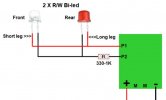
Hi, with the 2 wire bi-led, is this correct ??? Thanks (This image has changed to correct the connections)

Attachments
Last edited:
-
1
- Show all
No.
(Now yes, as above drawing has been corrected.)
You wire the LEDs (and resistor) between Pins 1&2..
Pins 1&2, are 3.5V when 'on' and 0V when 'off', so when you change direction the polarity of the voltage between Pins 1&2 changes.
PhilP
(Now yes, as above drawing has been corrected.)
You wire the LEDs (and resistor) between Pins 1&2..
Pins 1&2, are 3.5V when 'on' and 0V when 'off', so when you change direction the polarity of the voltage between Pins 1&2 changes.
PhilP
Last edited:
I changed the previous image. Any better ??No.
You wire the LEDs (and resistor) between Pins 1&2..
Pins 1&2, are 3.5V when 'on' and 0V when 'off', so when you change direction the polarity of the voltage between Pins 1&2 changes.
PhilP
Thanks Phil. Whats the old saying, a picture paints a thousand words. I was thinking how to get a negative into the circuit & forgetting P1 & P2 care swapping this side over every time you change direction with the train. Can also see Jimmy B's logic on coming off the motor as many might not be RC. Thanks for your patients guys. 
PS: have changed the image again.
PS: have changed the image again.
You got it. 
What did you use to draw your diagram?
I am still looking for something to do mine..
PhilP
What did you use to draw your diagram?
I am still looking for something to do mine..
PhilP
Hi PhilYou got it.
What did you use to draw your diagram?
I am still looking for something to do mine..
PhilP
Not sure what Chris uses but, as you know, I used to use PowerPoint. However, I recently had to buy a new laptop and baulked at the idea of paying an annual sub for MS Office. So, following GregH's advice, I downloaded and installed Libre Office which does everything MS Office does but also includes a very good Draw program.
Rik
-
3
- Show all
Its actually a WYSIWYG web page/site builder that i used to build many websites but moved on to WIX now as its free. The website builder is also free. Go to this page & download If you need any help let us know.,You got it.
What did you use to draw your diagram?
I am still looking for something to do mine..
PhilP
-
2
- Show all


