Brixham
No buffers were hurt at this sign
This is an early 2056, that has a ‘repaired in 1999’ label. So perhaps early 90’s
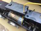
I used some yellow multi strand wire a very similar gauge to the already installed brown, green and white wires.
Drill a hole adjacent to the WS marked terminal from inside the motor block to outside.
Bend the motor contact through 90 degrees, and cut off any that protrudes.

Solder the yellow wire onto the terminal such that it is vertical.


Lower the top housing onto the 3 existing pins and feed the yellow wire through the new hole. Add some heat shrink just to be sure.

Check that there is NO electrical connection from the new yellow wire to the WS white pin.
Temporarily connect the new yellow cables to the white terminals, and check the loco runs under analogue, but now with 4 pin motor blocks


The black/red/ white cable is for the rear light cluster, red is common, black is reverse headlights, and white is marker boards.
The 4 way cable, green appears to be common, White is forward lights, brown is marker boards, and yellow is the rooftop flashing led. CAUTION.....ALL 5 volts, so cv’s need changing.
The two terminals sw and rt are for the track power bus sockets at the rear of the loco
I’ve not fitted a decoder yet, as I found an old lgb digital sound board, which works. I have a couple of analogue lines to visit, so will fit a speaker, reassemble, and run it for a while. Of course, I have to link the newly fitted yellow wire back to the white terminals on the sound board to revert to 3 pin mode
I used some yellow multi strand wire a very similar gauge to the already installed brown, green and white wires.
Drill a hole adjacent to the WS marked terminal from inside the motor block to outside.
Bend the motor contact through 90 degrees, and cut off any that protrudes.
Solder the yellow wire onto the terminal such that it is vertical.
Lower the top housing onto the 3 existing pins and feed the yellow wire through the new hole. Add some heat shrink just to be sure.
Check that there is NO electrical connection from the new yellow wire to the WS white pin.
Temporarily connect the new yellow cables to the white terminals, and check the loco runs under analogue, but now with 4 pin motor blocks
The black/red/ white cable is for the rear light cluster, red is common, black is reverse headlights, and white is marker boards.
The 4 way cable, green appears to be common, White is forward lights, brown is marker boards, and yellow is the rooftop flashing led. CAUTION.....ALL 5 volts, so cv’s need changing.
The two terminals sw and rt are for the track power bus sockets at the rear of the loco
I’ve not fitted a decoder yet, as I found an old lgb digital sound board, which works. I have a couple of analogue lines to visit, so will fit a speaker, reassemble, and run it for a while. Of course, I have to link the newly fitted yellow wire back to the white terminals on the sound board to revert to 3 pin mode
Attachments
Last edited: