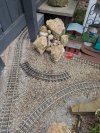
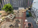
The Woodlock Line

Looks like it would work if you removed the pine, if you dig out enough roots they are fine to move around. I have done it a good few times and it has worked well. A good soaking for a few days before digging out and after wards makes a big difference in survival rates. Having 2 trains running at once would be pretty awesome. Hope it works out.
I'm sceptical. I just don't think the R1 will get around with getting too close to the existing line. Either way, it will become something interesting....
 
I can confirm, that's not going to work..... Anyone any experience of Heyns R0 corners? (Semi serious question)...... Y points would look good though wouldn't they, to form a triangle....PXL_20250514_131900530.jpg
 
You would be really pushing the envelope, if you went 'R0'..

Are you track-powered? - You will need a reverse loop unit, if you create a triangle.

PhilP.
 
You would be really pushing the envelope, if you went 'R0'..

Are you track-powered? - You will need a reverse loop unit, if you create a triangle.

PhilP.
Yeah, track powered. Nobody does Y points though. That's not what I want to do really. No experience of R0, I understand my field stock etc would happily go around them.
 
Looks like we're going R0 to make it fit. Realism wise, not too bothered, as it's not in an extremely visible part of the layout. It will be used for such as railcars, field stock, and generally short 4 wheelers, obviously testing smaller bogie stock. Either way it will add operational interest, and when the bigger stuff is out on the layout, then it will not travel over that section, and the railway will be used as it is now.

Thing is whether to purchase 3 set track from Heyn or to use LGB Flexi track bent to that radius with rail bender. Paul at PS has offered to do the latter for me. I have bent by hand and old knackered R1 to give me an idea in the pictures.PXL_20250514_180641520.jpgPXL_20250514_180643852.jpgPXL_20250514_180654087.jpgPXL_20250514_182314980.jpgPXL_20250514_182442833.jpgPXL_20250514_182442833~2.jpg
 
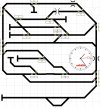
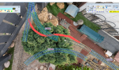
Which should, should result in this track diagram. I will just need some isolated fish-plates to stop the, what is now, and will remain a turning circle. The new points will be wired into number 5 points so that they co-act like a main to main crossover.

Screenshot_20250514-200328~2.jpg
 
Would it be worth try the flex track first rather than ordering from Germany?

If it doesn’t work the flex track nigh just end up in the spares bin/ wagon load etc

Dan
That's how I'm thinking.... This evening I've had a go at bending, by hand my two R1 corners to get an idea. For an effort by hand, I'm quite impressed. I will gauge test them tomorrow and try smoothing out with the tap of a hammer. I only need two R1s bending to the correct radius.
PXL_20250514_182442833~2.jpg
 
your curves under the fence dont line up properly.
I would take a longer turnout with a bigger radius for under the fence so your transaction curve wil have more tolerance.

For the piece "dead end line" i would place the turnout a bit futher down to the red stuff, even maybe the frog 4 inch/10cm after the red stuf, also here i would take a bigger radi turnout.

Then you would get away with tighter curves/transaction line between the two turnouts.

Two other ideas that require a bit more pain:

Place two new fence posts each 50cm/1.5feet away from the original fencepost and cut that one....
Or dig deep in your wallet and buy or make a crossover.
With the tight transaction curve s shape between your two new turnouts you can have clearance enough, but i am in doubt.

it can be done
can be done.png

start with cutting up the curve as you wish and put some flexitrack in the middle to connect them as a transaction curve.
i used a r0 turnout in this one but a r1 or r2 would be better.
Hope this was of any help

Ps for illustration i left the curves longer then they are ssuppost to be, i think 15cm/6inch would be more than adequte to start the transaction.
But it is tight....
Judging by the size of your cars, the clearance you have with the fence post would be enough.

best Igor
 
your curves under the fence dont line up properly.
I would take a longer turnout with a bigger radius for under the fence so your transaction curve wil have more tolerance.

For the piece "dead end line" i would place the turnout a bit futher down to the red stuff, even maybe the frog 4 inch/10cm after the red stuf, also here i would take a bigger radi turnout.

Then you would get away with tighter curves/transaction line between the two turnouts.

Two other ideas that require a bit more pain:

Place two new fence posts each 50cm/1.5feet away from the original fencepost and cut that one....
Or dig deep in your wallet and buy or make a crossover.
With the tight transaction curve s shape between your two new turnouts you can have clearance enough, but i am in doubt.

it can be done
View attachment 342574

start with cutting up the curve as you wish and put some flexitrack in the middle to connect them as a transaction curve.
i used a r0 turnout in this one but a r1 or r2 would be better.
Hope this was of any help

Ps for illustration i left the curves longer then they are ssuppost to be, i think 15cm/6inch would be more than adequte to start the transaction.
But it is tight....
Judging by the size of your cars, the clearance you have with the fence post would be enough.

best Igor
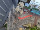
That's a brilliant bit of diagram. The red line I drew was purely to illustrate the route. The dead end to which it will link into will indeed be taken out and smoothed off with a slack corner, yet to be decided. I'm definitely not moving the fence posts :D .

Stay tuned.... Thanks for the diagram work, it's gave me some ideas.
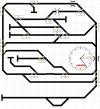
Have you thought of a secondary post to the right as seen above with the original bolted to it and cut off for clearance? May be tricky to get one on but metpost may be a saviour.
 
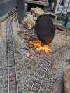
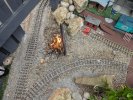
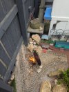
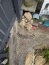
Progress report. The tree stump has been eradicated, whilst trying not to melt the signalling cables in the vicinity. My botched R0 curves give an idea, of what may be. Next stop to order 2 x Heyn R0 corners as they have been manufactured properly, and I'm not capable of bending rail, or have the correct tools. Obviously the route will have route restrictions, and doing it like this removes the need for yet more fence alterations. Moving the fence post would still not work, as there are railway sleepers right up to it if you remember from my first ever pictures.... So would still block the intended route.

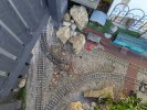
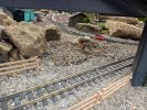
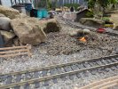
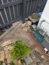
By the way, thanks for everyone's suggestions, I have considered them all. The photos don't entirely show the actual environment though to which I am trying to fit it in. I can't use larger points unfortunately as the driveway is to the other side, so R1 is absolutely essential. I've tried doing some more photos to give an appreciation of what surrounds the building site.

PXL_20250515_100717490.MP.jpgPXL_20250515_100726612.MP.jpgPXL_20250515_100745671.MP.jpgPXL_20250515_100748357.MP.jpgPXL_20250515_100958934.MP.jpgPXL_20250515_101130397.MP.jpgPXL_20250515_101322122.MP.jpgPXL_20250515_101327349.MP.jpgPXL_20250515_103145498.MP.jpgPXL_20250515_101442020.jpgPXL_20250515_103153027.jpgPXL_20250515_104556147.jpgPXL_20250515_104557749.jpgPXL_20250515_104559112.jpgPXL_20250515_104600648.jpgPXL_20250515_104746709.jpgPXL_20250515_104929549.MP.jpgPXL_20250515_105013269.MP.jpgPXL_20250515_110248885.jpgPXL_20250515_110252127.jpg
 
Have you considered connecting into the track on the left?

You can still get across to the other track, and could keep the siding / head-shunt on the right.

PhilP.
 
Have you considered connecting into the track on the left?

You can still get across to the other track, and could keep the siding / head-shunt on the right.

PhilP.
I have. Thing is, this is all about having two independent circuits, and if I joined it to the line on the left, it loses the benefit, that of effectively been double line, and would create a bottle neck that needed managing when running, to avoid crashes. And it would need a reverse loop module, not a problem, but not long enough to accommodate my length of trains without shorting the CS3, all my stock has metal wheels you see.Screenshot_20250514-200328~2.jpg
 
If you were to have a R1 curves starting immediately after the toe of the 3 Way Point and slewing/tightening the chord to the left, could that give you more room for the new chord to be R1?

I haven't seen a complete track plan, other than your graphical one for the CS3....
 
If you were to have a R1 curves starting immediately after the toe of the 3 Way Point and slewing/tightening the chord to the left, could that give you more room for the new chord to be R1?

I haven't seen a complete track plan, other than your graphical one for the CS3....
If I had a box full of R1 I'd try to do that I think or at least lay them out to get some ideas. It's a lot of money wasted though if it still didn't fit.
 
Back
Top Bottom