You are using an out of date browser. It may not display this or other websites correctly.
You should upgrade or use an alternative browser.
You should upgrade or use an alternative browser.
RhB signals
- Thread starter Loco
- Start date
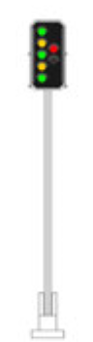
Loco said:Do or did RhB ever use this type of signal (with two columns)?
That appears to be a SBB signal of system L.
The official Swiss Federal signal handbook (R 300.2 A2008 d) can be downloaded as a Word file in any of the four official languages. The URL is cumbersome, so I suggest you search on the document reference. The most recent version referred to in the Swiss Parliament website is July 1, 2012.
The variety of aspects, used to display the various speed restrictions, is nicely illustrated at
http://www.hurrug.de/bahn/slhp.html
This is accompanied by two photographs confirming that only the required lights are installed, so the one with two red lights on the right column is the ‘all singing’ version.
My understanding is that the RhB have their own Signal Handbook and originally the different aspects showed routing information, rather than speed restrictions, but they are changing to the Federal standard.
As far as I am aware the only RhB vehicles with a top speed over 90km/h are the dual voltage Allegra (100km/h in normal service, world speed record for 1m gauge in the Vereina tunnel of 139km/h) so there would be little point in the three green aspect.
Its unlikely therefore that there would be any need for the configuration with seven lights on any RhB signal. Not that I make any claim to be expert on this.
In 2013 there were two serious accidents (on SBB) involving signaling and single track operation and there was some discussion about the replacement / upgrading of the Signum system and timescale on the SBB. Questions have also been asked in Parliament about the training and familiarity of non SBB employees (e.g. Swiss Cargo) but I suspect that was confined to the SBB network. There is dual gauge / dual SBB-RhB operation on some lines from Chur so this may affect RhB operations and signaling standards.
So to summarize -
No! (so far as I know)!
Loco
Registered
Thank you for the replies, very helpful in order to try to understand the RhB signal system. I have also read this thread by PaulRhB on the RMweb forum: http://www.rmweb.co.uk/community/index.php?/topic/39767-rhb-signalling-in-switzerland/ which was very informative as well. I was surprised that RhB use/used aspects for routing informaton rather than speed information.
I am in the process of making a prototype 3D-printed signal and it is very easy to make different versions when fiddling around, and that is why I asked the original question.
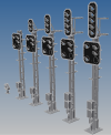
Here is a picture of some of the signals I have modeled so far and I have ordered the 3rd from the right. The one to the right is then possibly not used on the RhB since the 5 aspects are not requied.
I am in the process of making a prototype 3D-printed signal and it is very easy to make different versions when fiddling around, and that is why I asked the original question.
Here is a picture of some of the signals I have modeled so far and I have ordered the 3rd from the right. The one to the right is then possibly not used on the RhB since the 5 aspects are not requied.
Attachments
PaulRhB
This Way Up
Remember my article is on the older style signalling that is currently being replaced by speed signalling. Depends what era you intend to model ")
Once painted, even with extra layers if required, shouldn't the 3D print be protected from UV? I think the heat from the sun is more of a risk.
Once painted, even with extra layers if required, shouldn't the 3D print be protected from UV? I think the heat from the sun is more of a risk.
Loco
Registered
The 3D prints arrived today. Not happy with door to door delivery from Shapeways, and have received feedback from them that they are looking into other options. I want door to post office, so I can choose when I want to pick up the shipment and not stay home all day(s) waiting for something that might arrive (or not).
Ok, enough complaining. Here are the bits:
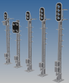
Main signal with 3 aspects + distant signal with 4 aspects. The dwarf signal can also be seen at the bottom right. At the left of the signal are two boxes, one of them is going to be attached close to the base on the signal.

Closeup of distant signal. It has angled shades with details. The upper left aspect has a clear Fresnel lens which will look good when everything is painted and with a LED inside.

Heat is probably an issue. The material used is Frosted Ultra Detail and is listed as heatproof to 80°C.
Ok, enough complaining. Here are the bits:
Main signal with 3 aspects + distant signal with 4 aspects. The dwarf signal can also be seen at the bottom right. At the left of the signal are two boxes, one of them is going to be attached close to the base on the signal.
Closeup of distant signal. It has angled shades with details. The upper left aspect has a clear Fresnel lens which will look good when everything is painted and with a LED inside.
Heat is probably an issue. The material used is Frosted Ultra Detail and is listed as heatproof to 80°C.
PaulRhB
This Way Up
One thought on heat distortion, could you leave a void, even two smaller ones, in the post to insert a piece of metal tube for stiffening? Make it a few fractions bigger diameter to allow for expansion so it doesn't split the print. You could even pass wires up the tube. Leave a piece if brass tube out in strong sun and measure it's diameter with a vernier.
Loco
Registered
There are already 2 voids, one in each rectangular tube. The size is only 1,6 x 4,6 mm per void, they were made with the intention of running up to 4 wires in each void for supply of power to the LEDs. There is also an opening in the center of the base as a spare solution to run wires in between the rectangular tubes, but wires there will be visible. So, unfortunately not much room to stiffen the signal posts.
Attachments
PaulRhB
This Way Up
Well you could do three wires in the void and a brass tube using that as the fourth contact, with one of the wires through the centre?
It could also act as a pin to locate the signals so they can be removed quickly at the end of a running session. Just a small 6 pin connector and two hard wired in to the tubes.
It could also act as a pin to locate the signals so they can be removed quickly at the end of a running session. Just a small 6 pin connector and two hard wired in to the tubes.
Loco
Registered
A few more pictures of the signals:
Assembly of most of the pieces and partly painted. The "banding effect" is visible on the column, this is caused by the printing process and is a very small difference in height in the FUD material. I am not sure if I have to sand it down or if I can apply more layers of paint to make it go away. I think I will try both methods to learn more.

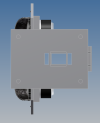
A small box (electrical box) is painted in a different colour. The box is hollow inside (shelled) to reduce cost. The FUD material is priced based on the volume used to make the part. It is supposed to be a much lighter grey colour which I don`t have at the moment. The second picture shows the box in the position where I will use epoxy glue to glue it to the column.


The main signal with 3 aspects consists of two parts, the plate with shades and the frame. This design allows the frame to be painted silver/grey first, then the front border can be painted white. The plate is painted matt black and then glued to the frame. An improvement of this design will be a plate with tubes for each aspect on the back side which will protect the LEDs from water and also prevent light from being visible from the rear side.

A small adjustment on the lower part of the black plate is required to make the two parts fit as this picture shows. It is already done, I just haven`t taken a picture of it yet.
You might wonder why I`m using a Pola bench for support, the reason is that a new RhB 3D model is being prepared...

Assembly of most of the pieces and partly painted. The "banding effect" is visible on the column, this is caused by the printing process and is a very small difference in height in the FUD material. I am not sure if I have to sand it down or if I can apply more layers of paint to make it go away. I think I will try both methods to learn more.
A small box (electrical box) is painted in a different colour. The box is hollow inside (shelled) to reduce cost. The FUD material is priced based on the volume used to make the part. It is supposed to be a much lighter grey colour which I don`t have at the moment. The second picture shows the box in the position where I will use epoxy glue to glue it to the column.
The main signal with 3 aspects consists of two parts, the plate with shades and the frame. This design allows the frame to be painted silver/grey first, then the front border can be painted white. The plate is painted matt black and then glued to the frame. An improvement of this design will be a plate with tubes for each aspect on the back side which will protect the LEDs from water and also prevent light from being visible from the rear side.
A small adjustment on the lower part of the black plate is required to make the two parts fit as this picture shows. It is already done, I just haven`t taken a picture of it yet.
You might wonder why I`m using a Pola bench for support, the reason is that a new RhB 3D model is being prepared...

Hi LOCODo or did RhB ever use this type of signal (with two columns)?
would you mind to share some of your 3D signal models, in particualr the 3-flame main signal.....
Bets regards
Thomas
Loco
Registered
Hi Thomas.
The links for components for the 3 aspects signal are here:
http://shpws.me/N3Yi
http://shpws.me/N3Yo
http://shpws.me/N3Yq
http://shpws.me/N3Yr
The links for components for the 3 aspects signal are here:
http://shpws.me/N3Yi
http://shpws.me/N3Yo
http://shpws.me/N3Yq
http://shpws.me/N3Yr
Thinking about UV protection. I have some small boxes that I got some time ago for my Wiring. They take a Choc Strip and effectively Box it up. Very useful for keeping things dryish. So a couple on the Layout were unpainted (clearish see through plastic) they have fallen apart completely with the UV Light. Another one was very much in your face so I sprayed it Black with Halfords Rattle Matt. Only one in perfect condition.
Wonder if an initial spray with the Matt Bkack then whatever finishing Colour decide would assist with the UV Protection?
JonD
Wonder if an initial spray with the Matt Bkack then whatever finishing Colour decide would assist with the UV Protection?
JonD
I guess it will also depend on the material you have them printed with??
I would think any decent (opaque) paint would do the job??
Not a fan of 'going black' due to the heat-gain in the sun.. I also find that other paints do not tend to take well to a black base-coat. YMMV, of course.
I would think any decent (opaque) paint would do the job??
Not a fan of 'going black' due to the heat-gain in the sun.. I also find that other paints do not tend to take well to a black base-coat. YMMV, of course.
Hi Thomas.
The links for components for the 3 aspects signal are here:
http://shpws.me/N3Yi
http://shpws.me/N3Yo
http://shpws.me/N3Yq
http://shpws.me/N3Yr
Hi Loko
I do have my own DLP-Printer. So I was interested in the CAD Data (e.g. stl) to print a signal for 0 scale.rather than by buy a finished product.
Best regards
Thomas
Similar threads
- Replies
- 3
- Views
- 396