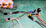
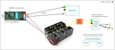
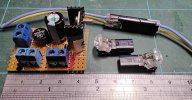
At the risk of being open to ridicule, here is my "no solder" lash up for what I propose. It's just to demostrate the circuitry not the actual installation. The assumption has been made that you're loco uses the usual LGB 5v incandecent 2 pin plug in lights : -
From top left : Battery pack which is connected direct to a +/- terminal block on the voltage regulator, on the right middle. Note the wires from that terminal block going back to RCT-Rx65, bottom left (do you have screw terminals on there or were they supplied already soldered on ?) You now have power for both your 6v lights and the variable voltage motor controller, built into RCT-Rx65c. Both are receiving at full battery pack voltage.
Looking at the voltage controller itself, over on the right again. See those two separate terminal blocks, side by side, front and center. These are for the 6v circuits, right for the output (+) and left return (-) points. One block (+) has 2 red leads coming out, these are the 6v power outputs. These wires will be connected, each to provide power to circuits for, 1 front set of lights and 1, your rear set.
Note the other terminal block, which would normally provide the return path (-) and complete 6v the lighting circuit, it's empty. Why ? See those two black wires next to those two red at bottom right. They would normally go in that terminal to complete the circuits. But here they bypass that terminal and are instead connected directly, and separately, to pads F1/A & F2/B, via those yellow and green wires on the other side of the connector they are attached to. The green is the return that completes the circuit to your front lights, when your loco travels forwards, as is the yellow to the rear set when going the other direction. It's important you connect your F & R lighting sets the right way around here.
Now the fly in the ointment that breaks the "no solder" dictate, there might be some extra wire required to get your F & R light sets into parallel wiring and to complete the lighting circuits as described. I suspect your RCT-Rx65c does not have those wires described soldered on F1/A & F1/B pads. However I know a man who can

P.M. me for that.
Couple of things. I notice from your pictures there appears to be a couple of chunky weights, each end behind the cabs. I can't find a manual (I looked at Tran-Li site) that shows a decent exploded veiw of this loco. Well, at least one of those big weights might be redudant, replaced with the weight of the battery pack. Makes a little more space to work with. My U Class had a stonking great weight filling most the boiler/water tank space, to provide for traction. Weight of battery pack made up for that. The other thing is that all that LGB circuitry gubbins is gone and no DPDT switch required. P.S. Anybody want a weight block for a U class and the circuitry boards and most wiring for one too ?

Max
View attachment 356977



 , especially if someone wants to run battery powered trains. Yes, there are Roundhouse battery locos but they cost fortunes. There are no reasonably priced (like £500) ready to run battery RC locos. When exists (like Piko switcher) it is a half hearted approach by manufacturer or sold as kit (so DIY again). But I understand price is subjective opinion and some people may enjoy DIY.


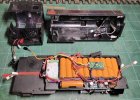
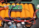

 I may travel to that side of the country in few weeks time and I shall PM you then.