LGB 2045 RhB loco review & questions

I have now converted this loco to RC battery power using MR603c receiver and Tx10 transmitter from RCtrains.co.uk. :D

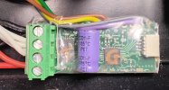
I removed all track power pick ups first. The motor block pins had white/brown/green plugged in. So I thought I can feed output from MR603C to there to get both motor and lights running.

Unfortunately this did not work. Somehow old LGB loco's circuit board did not like PWM DC output from MR603C. As a result, when I did this, the loco's wheels rotated at a very slow crawling pace irrespective of where my Tx10 controller dial was.

However, once I removed the existing wires from motor block and fed MR603c output only there the loco ran as expected. I can control the loco using Tx10. But lights are now off.

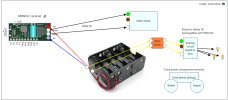
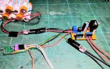
I need to figure out a way to power the lights. I checked that sending battery power to brown/white wires or feeding power via front/rear sockets do work. Either have to use a separate battery pack or I need to create a split (Y) connection from onboard battery pack and send a feed to light wires directly - with another path going to MR603c and then to motor.

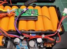
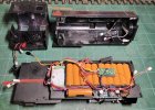
This loco has enough space inside but the 2 protruding connecting rods take up some space inside. They also move inside as the train runs - so had to secure my battery pack from hitting those rods, using a cardboard separator.
Well done Mobi. At last a proper conversion, no stopping you now. As for the lights. Hm not sure what the circuit biard is doing there may be some electronic gubbins in there sucking up all the power. Possibly as I did with an oldie was to follow the tracks in the board, disconnect where it disappears into components you do not understand. Then you could solder wires to the useful tracks and temporary join them up to the supply, your biard may have lighting outputs. If you use clips for temporary connections you should be able to get your lighting working as expected.
 
There are two ways to connect and have this running with minimal internal intervention:

1. Leave the motor block connections 'as is'. Feed the motor output wires of you MR603c to the two rear sockets.

2. Leave the White and Green wires connected to the motor block. Connect one of the motor output wires from the MR603c to the White wire connection on the motor block. Connect the second motor output from the MR603c to the Brown wire you have removed from the motor block pins.

There is a third option, which is to modify the internals of the motor block, to separate the motor terminal from the White track pickup, and bring a fourth wire out of the block. - You would have to do this, if fitting a DCC decoder.

There are outputs on the MR603c which can control the lights, but this requires extra wires to be soldered to the receiver.

PhilP.
 
I tried #2 but it didn't work - same problem of motor crawling even at full throttle.

#3 is beyond my skill level. :think:

#4 yes, I read that but I can't solder and if I try I'll probably mess it up.

What I dislike about G scale that it requires too much surgery :speechless:, especially if someone wants to run battery powered trains. Yes, there are Roundhouse battery locos but they cost fortunes. There are no reasonably priced (like £500) ready to run battery RC locos. When exists (like Piko switcher) it is a half hearted approach by manufacturer or sold as kit (so DIY again). But I understand price is subjective opinion and some people may enjoy DIY.

GRSUK wanted £450 to convert this loco to battery power and £750 including sound. These are serious amounts of money for me and hence I had to go with DIY conversion (under £100 route).
 
I tried #2 but it didn't work - same problem of motor crawling even at full throttle.

#3 is beyond my skill level. :think:

#4 yes, I read that but I can't solder and if I try I'll probably mess it up.

What I dislike about G scale that it requires too much surgery :speechless:, especially if someone wants to run battery powered trains. Yes, there are Roundhouse battery locos but they cost fortunes. There are no reasonably priced (like £500) ready to run battery RC locos. When exists (like Piko switcher) it is a half hearted approach by manufacturer or sold as kit (so DIY again). But I understand price is subjective opinion and some people may enjoy DIY.
GRSUK wanted £450 to convert this loco to battery power and £750 including sound. These are serious amounts of money for me and hence I had to go with DIY conversion (under £100 route).
Probably (way) beyond your price point, but PIKO are introducing some steam locomotives preconfigured for DCC, sound, battery power and R/C. US outline, but available in Europe. Most of the electronics are probably stuffed in the tender, so it may be a while before European outline locos are available. At one US website the price premium for DCC, sound and the battery setup is about $450 over a straight DC loco. Be interesting to see how well they sell.

Tri-Mode Sound, An Industry First from PIKO!

Conceived by PIKO in response to customer requests, these new locos join proven PIKO R/C with cutting-edge TCS digital technology, offering steam locos with smoke and digital sound, factory-equipped for operation on your choice of:

  • DC Track Power
  • DCC Digital
  • Onboard Battery Power with R/C
For easy Battery R/C operation, insert (10) AA rechargeable cells (not included) into the battery clip in the tender. Non-rechargeables will give poor performance and are not recommended! 2800 milliamp-hour rechargeables are readily available and should give over two hours of run-time with smoke on and sound at full volume.
Or, connect standard 14.8V or 18.5V 3400 milliamp-hour rechargeable lithium battery packs, available from various G-Scale retailers, to the industry-standard JST connector socket, for many hours of run-time. 14.8V packs should give all the top speed you need. 18.5V packs can give a bit longer run-time.
Control speed, direction, emergency stop, bell and playable whistle with the included PIKO R/C Pocket Remote.

Both DC and Battery operation offer a wealth of automatic digital steam sound features, like exhaust chuff, air pump, and more. Bell and whistle can also be activated by track magnets, such as PIKO #35268. KeepAlive® technology keeps everything running smoothly even over dirty track on DC/ DCC power, and provides standstill sound in all three modes.

DCC operation offers even more features, plus all the benefits of TCS WOWSteam Sound. Choose from numerous bells, whistles, exhaust chuff sounds and more! Audio Assist® easily guides you through programming without the need to memorize CVs. Sound choices made on DCC also remain in effect on DC or Battery R/C operation.
 
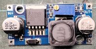
I am probably talking out of turn here. I converted an old LGB 2171D U class variant recently to battery/rc. Same 3 wire system, green/white/brown with its circuit boards and 5v regulator and switches. No worries about converting back. So......Using a similar Micron 65c card to yours, my approach.....gut it ! I retained the 5v incandecent directional lights and 5v Seuthe smoker. Motor is now controlled directly, 2 wires, 1 in 1 out, from Micron. Attached and fed a DC - DC buck with full battery current, adjusted to 6v output. Returns from, separate front and rear light circuits, soldered to appropriate pads on Micron to retain directional capability. Returns on Seuthe smoker and cab light back to - output on buck, Seuthe is via an on/off switch. Simples (with a lot of help from PhilP !) Max

General overview of the converssion. Switchgear and fuse out of sight at the top. Sockets at the rear for directional and cab lights, also speaker. 2 sockets in the air, at the front, for front lights and Seuthe smke uniy. It's got MLS soundcard in the middle with its remote sticking up.
20260406_210704.jpg
Close up around the DC - DC buck, Seuthe's switch. You can see 3 wires on the Microm 65c. 1 is a sound trigger, the other two are the front and rear light circuit returns. Please don't ask me which pads I soldered to. But I think I know someone who can.....PhilP (sorry Phil)
20260406_210813.jpg
Quick little test run, first time of asking.
 
I converted an old LGB 2171D U class
Your skill is 10x better than mine :D
What that single battery on the side for - as well as the blue circuit board?
Are your batteries fixed into position or you need to take the top of the loco to insert them?

In my case batteries are removable and hence I can't screw the roof of the loco permanently. :think: I'll sort out the lights soon but no sound for me. I use a primitive solution like keeping my mobile on a wagon and pretend sound is coming from the loco :giggle:

Here is a video of loco after the conversion running indoor. I also ran it outdoor and worked fine (outdoor has been too hot lately).

 
Your skill is 10x better than mine :D
What that single battery on the side for - as well as the blue circuit board?
Are your batteries fixed into position or you need to take the top of the loco to insert them?

In my case batteries are removable and hence I can't screw the roof of the loco permanently. :think: I'll sort out the lights soon but no sound for me. I use a primitive solution like keeping my mobile on a wagon and pretend sound is coming from the loco :giggle:

Here is a video of loco after the conversion running indoor. I also ran it outdoor and worked fine (outdoor has been too hot lately).

Thank you. Little skill involved, I'm just a tidy freak. Ok, this is my 7th conversion, but they are mostly not the same. Everything you see here is mounted on heavy duty Gorrila double sided tape. All orange jacketed batteries are all part on the same 11 AA cell NiMH pack. 10 cell and single cell styrene trays (don't ask why not in shrink wrapped pack, long story). It's just the way they had to be done to fit under the body. Yes, the switch and charger sockets had to be drilled. I use a stepped drill cutter, mounted on a slow speed electric screwdriver (lots of torque) to do the circular ones.

Blue thing, bottom left hand, is the DC - DC buck, aka voltage regulator. I use a DC - DC buck but I could, as I have done where supplied, use the onboard voltage regulator to supply lower voltage accessories. Full battery pack voltage goes in one side of the buck, 6v comes out the other. It's adjustable, it's the teeny little brass screw on a small blue tower that adjust. Just connect output to voltmeter (multimeter) twiddle the screw and Bob's your uncle, voltage you want comes out the other side.

Body fits on with original set of 6 screws. However, battery pack could be mounted in trailer and connected to all the other bits, keeping the on/off, charger, fuse on board loco, with something like a JST connector. This solution I have used on a couple of conversions so far where there was insufficient space to mount conventional batteries on loco. I use an old Aristocraft 20ft gondola converted for that purpose. Just clips in to a trailing lead coming out the loco. Too much information :D Hope this helps. Max

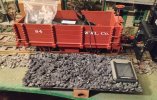
Below. My, very multi-purpose gondola. You can just make out a 16 AA cell NiMH rechargeable pack sitting in there. Just the pack no other gubbins associated with battery conversions, those are on the locos. Look to the right, down by the coupling, and you can see the red JST connector attached to another coming from the loco. This loco has connectors fore and aft so trailer can be on either end. That's your full battery voltage going to the ESC and any other accessoires, with or without a voltage regulator.

The gondola also functions as a match wagon connecting with swappable couplers either end, knuckle (2 heights, 15 mm scale NAMR or USAT/Aristocraft/LGB/ Bachmann), link & pin, hook & loop (LGB, etc') and 16mm scale type dumb centre buffer and chopper. Anything to anything. Oh, and it's a speedometer/odometer car too. That's sitting on the coal load, its reed sensor reads a tiny neodynium magnet fixed to one of the wheels. It's set to measure at 1:20.3/15 mm scale speed, but it can be recalibrated for any scale ! Fun or what ?
20251118_110425.jpg
 
I researched why the this loco's original circuit board cannot handle output from MR603 circuit.

This is summary from Claude AI so I don't know whether it factual or hallucination. So reader discretion is advised. :think:

Old West German-made LGB locomotives (like the 2045) were built when smooth DC was the only control method. To comply with strict West German VDE radio interference regulations, small ceramic capacitors were fitted directly across the motor terminals on the circuit board. Their job was to suppress the high-frequency electrical noise generated by motor brush sparking, which would otherwise interfere with AM radios.

The problem is that PWM speed controllers (like the MR603 in a battery-powered conversion) work by sending rapid on/off pulses to the motor block. Those ceramic caps cannot distinguish between unwanted motor noise and the intentional PWM pulses — to a capacitor, both look identical. So the caps dutifully filter out the PWM signal, leaving the motor with only a weak averaged voltage. The result is the loco crawling at full throttle.

Bypassing the board and feeding PWM directly to the motor confirms this — the motor runs normally without the caps in the signal path.

Later LGB models don't have this problem because the caps were removed when DCC became standard. A DCC signal is also a high-frequency pulsed waveform, so the suppression caps would have prevented DCC from working entirely. Suppression was instead moved into the decoder itself, designed to block motor noise without affecting the control signal.
 
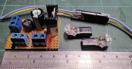
There is a way around issues with PWM feeds to "devices" that don't like it. Way above my pay grade. However I understand they are a form of "bridge rectifier". Initially a forum member here, John Scanlon, produced one for me, sadly no longer on here. I then used ones produced by the Australian company RCS, an SSI-9 in their catalog, just a little device but sadly now long out of production (prop Tony Walsham sadly passed around 5 years ago). When I ran track powered I could run direct non PWM current. However when I went battery/rc that was not an option. In my application it was used to "smooth out" the PWM current from an ESC controlling the output of the old Sountraxx Sierra sound cards I liked to use. Without it the sound cards would operate somewhat erraticaly. It was that or ditch the cards. Current from both the battery pack (reduced to the 6v DC back up voltage for the sound card) and variable voltage output from the ESC were fed through it to the Sierra card. Max
 
Back
Top Bottom