
Building the PS Models Boxcab Loco Kit

I recently came across the Phil Sharples website & he offers a range of kits at budget prices aimed at the 16mm 32/45mm garden rail enthusiast.
I ordered the Boxcab Loco kit & it arrived within a couple of days, full instructions are included with the kit, all that is needed is some PVA glue for the MDF parts, super glue for the 3D printed parts, some paint & a little time to assemble the kit. On first inspection, all the parts are supplied in little ziplock bags, with some nicely detailed parts. I also ordered the optional four wheel drive kit, which is not included with the loco kit.
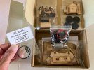
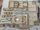
IMG_4676.jpeg


IMG_4677.jpeg
 
One of the joys of this and many other hobbies, those artisan creators, with their imagination, skills, creativity, ingenuity and determination. Long may they prosper and proliferate. And the new technologies available now will let almost any contribute it they choose.
 
A quick glance over the assembly instructions & it’s clear this little loco could be possibly built over a couple of evenings. But that takes all the fun out of it, I’m going to take my time & enjoy the build. Some parts I will paint before assembly, to hopefully give a neater finish. Ok so the first thing I noticed was the motor unit was an extremely tight fit in the mounting hole, almost to the point of breaking the MDF, I was having to use that much force. The instructions do suggest lightly sanding parts to fit, so some fine emery & a piece of dowel was used to very slightly open up the motor mounting hole, until the motor slid into place easily.

IMG_4678.jpeg

IMG_4679.jpeg
 
The loco can be configured to run on either 32mm or 45mm track. There is provision to mount the chassis rails at the correct spacing depending on your track gauge. My track is 45mm so the outer slots were used to glue the rails in place. The chassis rails also support the end of the motor, so if the outer slots are used, two additional pieces must be glued in place to the inner slots, as shown below. Once the bearing bushes were pressed in & chassis rails were glued in place, the end frames were added. At this point everything has fit together nicely & the tabs line up with the slots perfectly, it’s all coming together to form a fairly sturdy little unit.

IMG_4680.jpeg

IMG_4681.jpeg
 
The buffer beams have outline rivet detail marked on them. I thought I would take this a step further & add some faux ‘rivet heads’ in the form of adhesive pearls available from Hobby Craft. For £3.50 you get a huge amount which should be enough for more than a few locos !

IMG_4682.jpeg

Three different sizes of pearls are supplied in the packet & the smallest size seems the perfect scale to give the impression of rivet heads. The pearls peel off the backing paper as a strip, so each one is carefully removed with a pair of tweezers & sent flying across the room never to be seen again. Another try with a spot of super glue holds each one in place.

IMG_4683.jpeg
 
The buffer beams have outline rivet detail marked on them. I thought I would take this a step further & add some faux ‘rivet heads’ in the form of adhesive pearls available from Hobby Craft. For £3.50 you get a huge amount which should be enough for more than a few locos !

View attachment 359316

Three different sizes of pearls are supplied in the packet & the smallest size seems the perfect scale to give the impression of rivet heads. The pearls peel off the backing paper as a strip, so each one is carefully removed with a pair of tweezers & sent flying across the room never to be seen again. Another try with a spot of super glue holds each one in place.

View attachment 359317
Not sure what material the expensive pearls are md from, but with plastic rivet heads, I had some success spearing them in the centre with a very sharp craft knife - they hang on long enough to be put in place.
 
Not sure what material the expensive pearls are md from, but with plastic rivet heads, I had some success spearing them in the centre with a very sharp craft knife - they hang on long enough to be put in place.
I would think they’re soft enough to be speared with the point of a craft knife, so I will try that tip as there is more rivet detail to add to the back of the cab. Thanks for the suggestion.
 
I would think they’re soft enough to be speared with the point of a craft knife, so I will try that tip as there is more rivet detail to add to the back of the cab. Thanks for the suggestion.


If that doesn't work, then maybe a pen or pencil with a little blob of blu-tack on the end...? Just a light touch to pick up the small item, but releases easily once said item is in place.

Tacky Wax will also work very well...

Jon.
:)
 
If that doesn't work, then maybe a pen or pencil with a little blob of blu-tack on the end...? Just a light touch to pick up the small item, but releases easily once said item is in place.

Tacky Wax will also work very well...

Jon.
:)
I will try the blu-tack also…
All great advice, thank you
 
I use the Cambrian Rivets where I do the craft knife trick and a blob of Superglue on a piece of plastic, sometimes the rivets to nit release on the work so a very small screwdriver helps.
 
I’m building a different PS 4w diesel kit, along with the 4w drive kit. Have to say it’s a very nice kit. Rightly or wrongly I painted all the MDF parts with MDF sealer before starting construction.

I’ve got the chassis built and it runs fine on 2 AAA batteries as advertised. However, I’ve bought a cheap remote control kit, one of those garage door openner type controls with just forward, stop, reverse and no speed control. Although this unit is advertised to work off 3 volts (same as loco), it actually needs 4.5v, which means the loco runs too fast. So I’m currently stuck with two problems, first where to put the third AAA battery, second how to reduce the output from the remote control chip from 4.5v to 3v. All the voltage dropping chips I can find have to have the + and - power supply to the correct terminals, while the output of the chip swaps polarity to change direction.

I expect you’ll complete your loco long befor I do.
 
.....second how to reduce the output from the remote control chip from 4.5v to 3v. All the voltage dropping chips I can find have to have the + and - power supply to the correct terminals, while the output of the chip swaps polarity to change direction.


A bit of a "bodgy" suggestion, but if space isn't a problem then maybe just two voltage droppers with diodes on both feeds, one for forward and one for reverse? Between the control chip and the motor of course.

Sure someone will have a more elegant solution, this was just the first one that popped into my head....

Jon.
 
I’m building a different PS 4w diesel kit, along with the 4w drive kit. Have to say it’s a very nice kit. Rightly or wrongly I painted all the MDF parts with MDF sealer before starting construction.

I’ve got the chassis built and it runs fine on 2 AAA batteries as advertised. However, I’ve bought a cheap remote control kit, one of those garage door openner type controls with just forward, stop, reverse and no speed control. Although this unit is advertised to work off 3 volts (same as loco), it actually needs 4.5v, which means the loco runs too fast. So I’m currently stuck with two problems, first where to put the third AAA battery, second how to reduce the output from the remote control chip from 4.5v to 3v. All the voltage dropping chips I can find have to have the + and - power supply to the correct terminals, while the output of the chip swaps polarity to change direction.

I expect you’ll complete your loco long befor I do.
Is that the new model with the 3D printed engine block ?

I probably should have used MDF sealer before the paint now you mention it, or at least sanded between coats… this is all a learning curve for me.
 
I probably should have used MDF sealer before the paint now you mention it, or at least sanded between coats… this is all a learning curve for me.
It all depends where you want to store it. The disadvantage with sealing first is that you are not gluing the MDF when you construct it - the strength of construction relies entirely on the strength of bond between the sealer and the MDF.

I have a personal preference for gluing before sealing/painting, however, the late, great, tac sealed his models before gluing without any apparent problems.
 
That's the one. In the picture you can see the remote control unit. The MDF sealer made the motor an even tighter fit and I had to use a sanding disc in my Dremel to get it to fit - which of course meant sanding off the sealer. I've primed it with Halfords rattle can.


IMG_8490.jpeg
 
That's the one. In the picture you can see the remote control unit. The MDF sealer made the motor an even tighter fit and I had to use a sanding disc in my Dremel to get it to fit - which of course meant sanding off the sealer. I've primed it with Halfords rattle can.


View attachment 359367
I shall be interested to know how you resolve the issue with the R/C.
I would also like to add R/C to the boxcar loco eventually. I already have the RC Trains Tx24 transmitter, so a receiver which will work with that would be ideal. I only need forward/reverse & variable speed control. Not bothered with directional lighting.
 
I shall be interested to know how you resolve the issue with the R/C.
I would also like to add R/C to the boxcar loco eventually. I already have the RC Trains Tx24 transmitter, so a receiver which will work with that would be ideal. I only need forward/reverse & variable speed control. Not bothered with directional lighting.
RCT-MR601 2.7V - 13V will do this.
You will need to fit a single Lipo, or three NiMH cells. *

* You can fit two, but would need to fit a booster.

PhilP.
 
Back
Top Bottom