HobbitFertang
Registered

Have you bench tested them??Currently on the workbench, err
Benches!View attachment 361122
Have you bench tested them??Currently on the workbench, err
Benches!View attachment 361122

 Deep breaths and relax, railcar etchings project has started, so first job drawing and comparing between the Accucraft and Worsley works to come up with a design for the chassis. The thinking at the moment is a heavy chassis for the light weight body, unpowered at this stage of head scratching?

Unpowered would mean that you wouldn't have the same problems as the prototype
View attachment 361169
I have this back of an old oven, which could be a good starting point, though it being galvanised could make for hard work?
 if you're going to run a pair
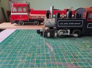
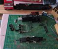
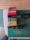
Stretch itMore or less finished with the drawings except for the power unit which will depend on if the Mauler chassis is suitable in running with the Accucraft railcar and can have it's wheel base extended or a new unpowered one made, anyway at least the wheels are the right size!
View attachment 361200View attachment 361201View attachment 361202


Galvanised could be better -I think solder will take to the zinc better than steel. Or am I confusing galv with tinplate?
View attachment 361169
I have this back of an old oven, which could be a good starting point, though it being galvanised could make for hard work?
Pete Just a reminder Galvanised fumes are poisonous and if you get Galvanised hot enough it will flare quite dramatically!Galvanised could be better -I think solder will take to the zinc better than steel. Or am I confusing galv with tinplate?
Cheers John/ @Northsider at this point still floating ideas, I will more that likely solder some brass angle to the body side and bolt that to the galvanised base, my soldering skills need to be proved on the etched brass side joins before we go much further!!Pete Just a reminder Galvanised fumes are poisonous and if you get Galvanised hot enough it will flare quite dramatically!
Brass is more difficult to solder than nickel silver because it conducts heat better.Cheers John/ @Northsider at this point still floating ideas, I will more that likely solder some brass angle to the body side and bolt that to the galvanised base, my soldering skills need to be proved on the etched brass side joins before we go much further!!

 . I used blue tac, and then tack soldered the joint until I was happy that it was fine and dandy, then I ran a fillet of solder down the joint ..................... that was quite a long time ago, possibly 20 years ago
Correct! As proven below, Mauler much too slow and gets dragged or shoved aroundUnpowered would mean that you wouldn't have the same problems as the prototype
 so it looks like plan C, an unpowered trailer set up, by the way,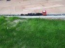
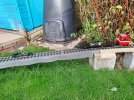


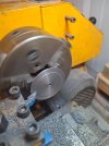
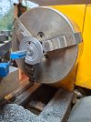
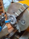
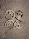
I might have a cunning plan on that front...@Fezwig, cant see you living with that short wheelbase option for long!
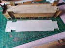
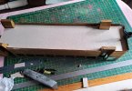
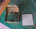
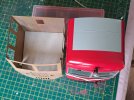
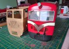


One of the difficulties of soldering brass, and it being a good conductor, is that when you go to solder the next piece, you can melt the nearby recently soldered joint.Today's installment, cutting card board! To check my drawing are correct before cutting metal, I did a dry run in cardboard, all good except the curve of the cab front needed a bit of adjustment.
View attachment 361297View attachment 361298View attachment 361299View attachment 361300View attachment 361301
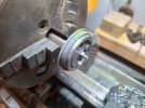
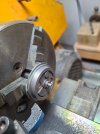
So next will be making up a list of jobs, ideas etc of how to make the thin etchings firmer, I have also had a brain (Barn?) storming session with my Northern friend in the South for the running gear, he has all the dangerous tool things I'm not allowed
 there's nothing to see
They likely use resistance soldering techniques, one if the many things that needed to se cleared out from Andrew's garage after he passed was a Resistance Soldering Kit, sadly went in the skip why I never saved it for my use I will never know.One of the difficulties of soldering brass, and it being a good conductor, is that when you go to solder the next piece, you can melt the nearby recently soldered joint.
Mole grips, or similar can be a good heat sink, to take the heat away from previously soldered bits, but you can also use 85 degree solder, which is used for white metal, for the tiny details if necessary.
I've no idea how Accucraft and others solder their models in the factory - all I know was that when I was using a Dremel to form an opening, a soldered joint started to melt
But I'm not telling which model was involved


