LGB new to this DCC help?

It's Orange and white based on LGB's wiring colour coding, The wire for points was Orange and White and the point switches were Orange. This was to help ensure people didn't cross connect things they shouldn't.
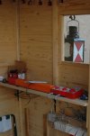
I worked that out reasonably quickly, I'm good at colours but electrically and electronically inept.

DSC_1827.JPG

This is after I tidied up the wiring :oops: ,that circuit board on the right was the automatic shuttle for the branchline. It was the original LGB item hidden in one of their buffer sections. Electronics outdoors? Er, no.
N.B. the LGB transformers were pretty quickly replaced by Gaugemaster 5 amp items with the cooling fan.
 
I worked that out reasonably quickly, I'm good at colours but electrically and electronically inept.

View attachment 346154

This is after I tidied up the wiring :oops: ,that circuit board on the right was the automatic shuttle for the branchline. It was the original LGB item hidden in one of their buffer sections. Electronics outdoors? Er, no.
N.B. the LGB transformers were pretty quickly replaced by Gaugemaster 5 amp items with the cooling fan.

I was sure you would would know, it was more for others that may not have known the wider picture of LGB switches and wiring components. ;)

It's great to see you controller setup, these things are often overlooked.

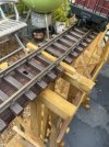
The lantern in particular looks fantastic.
 
I was sure you would would know, it was more for others that may not have known the wider picture of LGB switches and wiring components. ;)

It's great to see you controller setup, these things are often overlooked.

The lantern in particular looks fantastic.
Its a fab lantern. Also what a great opperation shed.
I'm putting mine in a mini green house to keep it dry.

So this orange and white marking is where I wire to a decoder so I can switch it remotley?
As far as I have heard a massoth decoder will do five points.

Is this point motor ok out in the weather or do I need to build a little shed over it?


Oh and Pugwash your wiring looks fab.... Im so rubbish at understanding it. But I will get there.

Im thinking of running two wires under the track with the odd connection as I read that wire moves the power faster than the track head.
I think this is called a "bus" in model world?

great heat today Im in the garden putting up my bents / trestles. As much as I have planned the layout on Railmodler express, I feel its now time to put up the trestles and Im guessing I can cut some track to fit.

Thanks
Chris
 
I worked that out reasonably quickly, I'm good at colours but electrically and electronically inept.

View attachment 346154

This is after I tidied up the wiring :oops: ,that circuit board on the right was the automatic shuttle for the branchline. It was the original LGB item hidden in one of their buffer sections. Electronics outdoors? Er, no.
N.B. the LGB transformers were pretty quickly replaced by Gaugemaster 5 amp items with the cooling fan.
It looks amazing. Ive gone DCC will this save me from complex electronics...... ?
To my knowledge, I just have to have good power to the track and the decoder will sort it out?

My track will be 6 meters by 2.5 meters. So not huge but outside and two turnouts.
 
Hi Chris and welcome to the funny farm, or forum as we like to call it.
I expect the digital whizzes will help you out but for that connecter plug I had one between a loco & tender which broke off just as yours has. The part is readily available and the fitting is easy, the connecter has teeth which go through the insulation of the wire and make contact with the core - no soldering! I think the wires snap off where they enter the plug due to being constantly flexed, they certainly were on my Nicki & Frank S.
We managed to fix the plug it actually was easy and lesson learnt.

Decoder is in and working good.

I kept blowing bulbs in my carrages.... but it turned out my model chap had mixed them up when he attended shows.... so now I have the 18 v bulbs we are all good.

Im learning as i go but so far DCC in bulbs sorted controller .... getting there.
Next is new track head and given the weather its so so time.

x Chris
 
Oh and rail modeller express is good but you can only place 50 items before you need to pay.
Any other ideas?

I think I have over thought the planning as while ive started putting up trestles its started to move ...... so I suppose its a good guide but don't get uptight about it.
When these real tracks were cut they had to adapt to the landscape. x
 
It looks amazing. Ive gone DCC will this save me from complex electronics...... ?
No, it was the LGB EPL system which was basically electrics with magnets and reed switches in the track to create electrical impulses. The wiring for it all looked like a nasty accident in an Italian restaurant - spaghetti everywhere.
For DCC a decent control system with a decent power output (I replaced my transformers with 5A units and was glad of it) decent decoders and decent contact between those should cover it. Outdoors I can't say but my indoor HO layout works and even though very small I have a lot of power/signal to track sections, maybe belt and braces but easier to fit first time than having to tear up the layout later.
To my knowledge, I just have to have good power to the track and the decoder will sort it out?
A decoder on its own will not sort anything out, it has to be told what to do therefore the decent control system. By the same dint a loco or anything requiring electric power will not work if the power is not getting to it therefore enough power and a good feed are crucial.
Keep going, these are good questions.
 
Hi crazy gang, been a while....... so I may be wrong but can you not put videos on here?

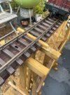
So the trestles are coming on in the garden. I have just done the first lifting bridge. So at one end a hinge which is working ok , at the other end I took a disk cutter and leveled one end so the track sits back flat with it.
Question is should I use some form of pin (brass maybe) to locate the track and help with the power?

Or is there an insert male female joint you have used before?

I dont think its mega important as im DCC so there will be lots of power I just felt if it helps then its prob good.
I can get brass rod and solder it in the under side of the track head facing down into a hole..... but is solder strong enough?

Hope your railways / railroads are going great.
Also thank you all your advise has got me going.

Oh I read that running some wire under the track as a "Bus" helps the power move faster around the track?

Ok happy Sunday and did you see Bryon Adams last night at radio two in the park? He was amazing 65 years old and looks amzing.


Thanks
Chris
 

Attachments

  • IMG_3837 Medium.jpeg
    IMG_3837 Medium.jpeg
    74.5 KB · Views: 0
  • IMG_3838 Medium.jpeg
    IMG_3838 Medium.jpeg
    69.3 KB · Views: 0
Hi crazy gang, been a while....... so I may be wrong but can you not put videos on here?

So the trestles are coming on in the garden. I have just done the first lifting bridge. So at one end a hinge which is working ok , at the other end I took a disk cutter and leveled one end so the track sits back flat with it.
Question is should I use some form of pin (brass maybe) to locate the track and help with the power?

Or is there an insert male female joint you have used before?

I dont think its mega important as im DCC so there will be lots of power I just felt if it helps then its prob good.
I can get brass rod and solder it in the under side of the track head facing down into a hole..... but is solder strong enough?

Hope your railways / railroads are going great.
Also thank you all your advise has got me going.

Oh I read that running some wire under the track as a "Bus" helps the power move faster around the track?

Ok happy Sunday and did you see Bryon Adams last night at radio two in the park? He was amazing 65 years old and looks amzing.


Thanks
Chris
Not directly, you put them to YouTube then copy the link and paste that into your post. Some have done vids by other routes but again only accessed via a link. Have only ever done YT myself.
 
Hi crazy gang, been a while....... so I may be wrong but can you not put videos on here?
No, it was the LGB EPL system which was basically electrics with magnets and reed switches in the track to create electrical impulses. The wiring for it all looked like a nasty accident in an Italian restaurant - spaghetti everywhere.
For DCC a decent control system with a decent power output (I replaced my transformers with 5A units and was glad of it) decent decoders and decent contact between those should cover it. Outdoors I can't say but my indoor HO layout works and even though very small I have a lot of power/signal to track sections, maybe belt and braces but easier to fit first time than having to tear up the layout later.

A decoder on its own will not sort anything out, it has to be told what to do therefore the decent control system. By the same dint a loco or anything requiring electric power will not work if the power is not getting to it therefore enough power and a good feed are crucial.
Keep going, these are good questions.
Hi been a while... my fault.
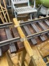
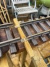
The trestle bents are going in ok... ish. I have this joint at the opening end of a bar hatch type lift section.
I think it should be ok if I run two bus wires to feed the lift end. I read that wires move the power faster than the track head so a bus wire is a good idea?

Have learnt some bits about soldering... seems ok ish.... or should i get LGB track conectors from the bus as then if I need to move the track we can just unscrew?

Another silly question no doubt.

Thanks
Chris
 

Attachments

  • IMG_3837 Medium.jpeg
    IMG_3837 Medium.jpeg
    74.5 KB · Views: 0
  • IMG_3838 Medium.jpeg
    IMG_3838 Medium.jpeg
    69.3 KB · Views: 0
Hi crazy gang, been a while....... so I may be wrong but can you not put videos on here?

Hi been a while... my fault.
The trestle bents are going in ok... ish. I have this joint at the opening end of a bar hatch type lift section.
I think it should be ok if I run two bus wires to feed the lift end. I read that wires move the power faster than the track head so a bus wire is a good idea?

Have learnt some bits about soldering... seems ok ish.... or should i get LGB track conectors from the bus as then if I need to move the track we can just unscrew?

Another silly question no doubt.

Thanks
Chris
You can post the link to your video if it's hosted on something like YouTube (other video apps available)....
 
It is good practice:
To arrange that there is an arrangement that isolates the track on the approaches to a lift / removable bridge..
This means the train should (hopefully) come to a stop, rather than looking like something from a Tom Cruise production, should a train be driven towards an open / removed bridge..

A bit of a faff, but easier than trying to find all the bits, and put them back together.

PhilP.
 
So my first video linked from utube as advised. Did it come pork as it will help getting advise.
I’m convinced now so long as the lift is powered from the hinge end this end should be a k as power on the bus will also be coming the other way…. So try and see then change.
Kathy Millet amazing model maker suggested two magnets which are like a doughnut with a bit that slots in the centre. May be a good idea as it will keep the lifting end in line and conduct power.
But thinking test and see.
Got a long way to go yet to get the full loop in.
But pleased so far.
Sorted lights for carriages turned out at 18v DCC lovely Dave had mixed up his bulbs at shows…. So get another and that won’t blow in 30sec
Also can I split off a feed from bus to feed my buildings?

You bunch have been so helpful
You could almost write a beginning guide to the start questions and just ping it as I feel I’ve learned much from you all.

James at massoth also so so helpful.

Thanks
Chris
 
Good heavens W walkerart you are advancing by leaps and bounds! I'm impressed and keep it going. If you stay analogue or go ditgal (in my opinion future proofing your current ideas) you are definitely going well.
But where are the pictures? On this forum if there aren't any pictures it didn't happen. ;)
 
Excellent, but why on earth did you cut the fishplate? Certainy soldering or any of the methods mentioned previously will work but a simple fishplate should too. Unless one of the original fishplates was dodgy to start with then a replacement might be the easiest option. Of course the other guys will shoot me down in flames now. :worried:
 
Back
Top Bottom