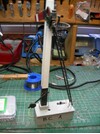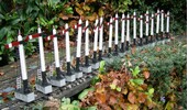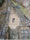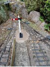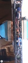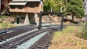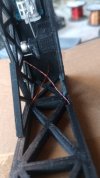
3D Semaphore Signals

Time for an update on the signals that were installed last year.

First the bad news. Out of the 4 signals only 1 remained working after the damp winter.

The good news is that all of the newer versions did not have any moisture in them. The single older version had a fair bit of moisture in its base. So I am pleased that the changes that I made to drain moisture at the top of the signals have worked. This was the first prerequisite of the signals, not to fill up with water.

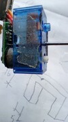
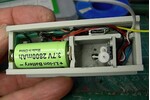
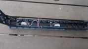
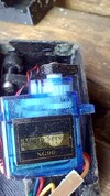
Some of the servos had signs of condensation on the inside of their cases -
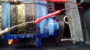
IMG_20260322_122122853_HDR.jpg
IMG_20260322_122822633_HDR.jpg

Users of servos in radio controlled models are concerned about using them in the rain and protection against splashes. After their use outdoors they are stored in a dry and stable environment.
In the railway garden we want to leave the servos outside 24/7 where they are subject to extremes of temperature and the rapid warming by sunshine. This rapid warming leads to condensation and is a cause of failure.

There are a lot of ideas and materials for waterproofing servos but they are for applications that are concerned about direct slashes of water and they don't have the issue of leaving their models outdoors 24/7.

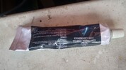
Looking at waterproofing products I came across a material called "Conformal Coating". There is a selection of materials, including acrylic, resin and silicone. They all work by being of low viscosity that easily flows and sets to protect PCB's from damage. The silicone version makes a thick, flexible covering to give excellent protection from moisture. They are made to waterproof circuit boards, the ideal solution for outdoor servos.

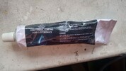
I ordered the silicone in a tube. Conformal Coating
IMG_20260402_181050344_HDR (1).jpg

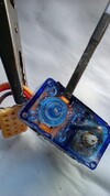
To apply the Conformal Coating, I had to dismantle the servos.

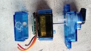
Removing the tiny screws, the top cover comes off, exposing the circuit board and also the bottom cover with the gears.

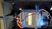
This left the centre section that contained the motor and potentiometer -
IMG_20260402_181510383.jpg
The top cover in this photo has holes in it's sides, I am trying out ventilation fitted to a pair of servos as a test.

Then I had to remove the motor, circuit board and potentiometer from the centre case.
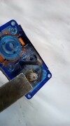
These are a tight fit in the casing but pressed out by pushing a screwdriver flat on the tiny gear and a smaller screwdriver to ease out the orange tabs of the potentiometer -
IMG_20260328_120814036.jpg
IMG_20260328_120914412.jpg
Note the signs of a rusty motor in the photos above. This is the servo removed from the early signal version that contained a lot of moisture.

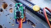
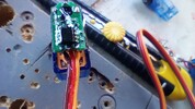
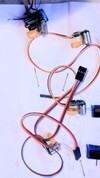
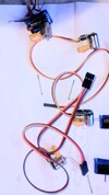
I prepared 4 servo boards to be coated avoiding the potentiometers. The top one is removed from the last working signal -
IMG_20260326_111215807~2.jpg

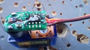
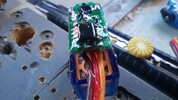
The Conformal coating was then applied straight from the nozzle covering both sides of the circuit board. The gel flows readily over the components and left a smooth self levelling layer over the board. It is totally transparent and can only be seen by the light reflecting off the gel -
IMG_20260326_112935161.jpg
IMG_20260326_112953741.jpg

The boards were covered so effectively that I think that they could be immersed in water and still work, especially if a second coat were applied for security.

I will now re-assemble the 4 signals and return them to their places for another 12 months feeling optimistic about their chances of survival.

In the meantime I have some more signals to make for other locations around the railway ;)

Alan
 

Attachments

  • IMG_20260326_113037056.jpg
    IMG_20260326_113037056.jpg
    216.2 KB · Views: 2
  • IMG_20260326_111215807~2.jpg
    IMG_20260326_111215807~2.jpg
    148 KB · Views: 2
  • IMG_20260402_181050344_HDR.jpg
    IMG_20260402_181050344_HDR.jpg
    380.3 KB · Views: 2
  • IMG_20260322_122154142_HDR.jpg
    IMG_20260322_122154142_HDR.jpg
    260.9 KB · Views: 2
  • IMG_20260328_121039785.jpg
    IMG_20260328_121039785.jpg
    138.7 KB · Views: 2
  • IMG_20260326_112640155.jpg
    IMG_20260326_112640155.jpg
    235.1 KB · Views: 2
Time for an update on the signals that were installed last year.

First the bad news. Out of the 4 signals only 1 remained working after the damp winter.

The good news is that all of the newer versions did not have any moisture in them. The single older version had a fair bit of moisture in its base. So I am pleased that the changes that I made to drain moisture at the top of the signals have worked. This was the first prerequisite of the signals, not to fill up with water.

Some of the servos had signs of condensation on the inside of their cases -
View attachment 354698
View attachment 354700

Users of servos in radio controlled models are concerned about using them in the rain and protection against splashes. After their use outdoors they are stored in a dry and stable environment.
In the railway garden we want to leave the servos outside 24/7 where they are subject to extremes of temperature and the rapid warming by sunshine. This rapid warming leads to condensation and is a cause of failure.

There are a lot of ideas and materials for waterproofing servos but they are for applications that are concerned about direct slashes of water and they don't have the issue of leaving their models outdoors 24/7.

Looking at waterproofing products I came across a material called "Conformal Coating". There is a selection of materials, including acrylic, resin and silicone. They all work by being of low viscosity that easily flows and sets to protect PCB's from damage. The silicone version makes a thick, flexible covering to give excellent protection from moisture. They are made to waterproof circuit boards, the ideal solution for outdoor servos.

I ordered the silicone in a tube. Conformal Coating
View attachment 354706

To apply the Conformal Coating, I had to dismantle the servos.

Removing the tiny screws, the top cover comes off, exposing the circuit board and also the bottom cover with the gears.

This left the centre section that contained the motor and potentiometer -
View attachment 354702
The top cover in this photo has holes in it's sides, I am trying out ventilation fitted to a pair of servos as a test.

Then I had to remove the motor, circuit board and potentiometer from the centre case.
These are a tight fit in the casing but pressed out by pushing a screwdriver flat on the tiny gear and a smaller screwdriver to ease out the orange tabs of the potentiometer -
View attachment 354690
View attachment 354691
Note the signs of a rusty motor in the photos above. This is the servo removed from the early signal version that contained a lot of moisture.

I prepared 4 servo boards to be coated avoiding the potentiometers. The top one is removed from the last working signal -
View attachment 354707

The Conformal coating was then applied straight from the nozzle covering both sides of the circuit board. The gel flows readily over the components and left a smooth self levelling layer over the board. It is totally transparent and can only be seen by the light reflecting off the gel -
View attachment 354693
View attachment 354694

The boards were covered so effectively that I think that they could be immersed in water and still work, especially if a second coat were applied for security.

I will now re-assemble the 4 signals and return them to their places for another 12 months feeling optimistic about their chances of survival.

In the meantime I have some more signals to make for other locations around the railway ;)

Alan
Good job but I would have left them in a very dry place for 24 hours to ensure not even the slightest bit of moisture still inside, outside 24/7/365 will find it.
 
This is a great idea.
Another way to use conformal coatings is to encapsulate the whole servo without dismantling. This was common practice in aircraft components back in the day when I worked on them, we used to dip the components in polyurethane as well.
I am going to use a conformal coating on my servo control boards in a box out in the garden.
Did you use anything on the shaft where it enters the body? A smear of silicone grease can help form a water resistant barrier I have seen.

The ones I used glowed under UV light so we could confirm coverage.
I will most likely use this on my signals servos Clearcote DCA Modified Silicone Conformal Coating | Jaycar Australia
 
Last edited:
Interesting stuff. I'm afraid I chickened out of trying to make my signals waterproof and made each one self contained and removable.


Rik
 
Good job but I would have left them in a very dry place for 24 hours to ensure not even the slightest bit of moisture still inside
Yes I get where you are coming from but I couldn't be bothered :confused:. I think the problem is condensation due to sunshine heating a small enclosure such as a servo case.
Did you use anything on the shaft where it enters the body?
No I don't think it needs protection from water ingress. The servos are protected from direct rain etc.
The ones I used glowed under UV light so we could confirm coverage.
Yes I noticed that they were available but I don't have an UV light :D so didn't bother.Using the thicker gel type product you can see the coverage with the thickness of the coating rather than a thin spray coat.
The spray you suggested looks good.

Alan
 
This may be of interest re the bounce for the signals

Picaxe is a very versatile microcontroller; I find I am using them a lot lately ever since I found that ChatGPT can write the program in the blink of an eye just as long as you detail what you want it to do.
It is really good for controlling servos to precise positions for use with points and signals.
Hi

I have been working on getting a 3d printed version of Rik’s Peckforton semaphore signals using ATiny85 microcontroller to replace the Seeduino as that board seems overkill for the control of a signal and led. I have modified Riks code and use the same mini linear servos. Rik’s Peckforton bases hold the ATiny85 chip on a piece of perf board, with battery and RX. I promised Rik to share the code for the ATiny85 which I must do, I use a ZiF socket to program and test the chip before mounting in the signal base - again it needs a write-up and a wiring diagram as it is required to link the ATiny85 to a Arduino board for programming the chip from the Arduino IDE.
 
My semaphore signals have all been working reliably this year but the test will be next year in the spring after the cold and damp winter.

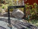
Earlier this year I have been making a pair of gantry signals situated at each end of the main station.
The main gantry was printed in a single piece and I did expect it to be a disaster because it was printed without any supports and it has a lot of unsupported pieces.
I used PETG and it came out not too bad and needed minimal cleaning up to remove whiskers of filament.

I designed the signal using linear servos glued to a base plate with mitred sides. The base then slotted into corresponding guides on the gantry -
IMG_20260820_154025905.jpg

These linear servos looked a good application because of their tiny dimensions allowing them to fit in the confined space inside the gantry.
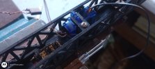
However, they were not strong enough to do the job, either just not working or constantly jittering. The open gearing was also vulnerable to tiny specks of debris that totally jammed the mechanism. So it was back to mrcro servos.

Fortunately I was able to adapt the signals without remaking the gantry to use conventional 9g servos. I made a clamp that slotted over the servo and was screwed to the base of the signal post -
IMG_20260820_115556970.jpg
The mounting tab on the opposite side was cut off and the gap for the servo between the side of the gantry and the mounting post was luckily exactly the correct size.
The servo wires were painted with black liquid tape to hide their bright colours,

Each signal required 4 wires, DC 5+, DC 0 volt and a control wire for each servo.

The 4 wires were run up through the inside of one of the legs, 2 wires per leg and are thus unseen.

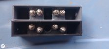
They connect at the base to a terminal block that was initially made too close together to tighten the nuts The terminal blocks were printed with a pause at the appropiate height and the M4 nuts were dropped into position before continuing with the print -
IMG_20260821_163948687.jpg

This base has a matching cover that is fixed to the gantry legs and drops over the base acting as weather protection

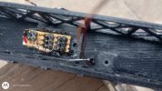
The wiring at the top of the gantry to the 2 servos and the 2 signal back lights was achieved by making a connector board that is glued to a mitred base that slides into position. The hole is for a clamping screw but the fit of the base was tight enough to not require it-
IMG_20260819_165359594_HDR.jpg

It has 6 pin headers. The four 3 pin headers are for power in and the servos. The two 2 pin headers are for the LED's with a resistor to reduce the power.

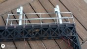
Soldered up some brass rod to make the railings -
IMG_20260819_165440900_HDR.jpg

The white signal posts were glued into sockets printed with the gantry.
The wires to the lights are routed through a hole inside the posts and emerge out of the sides of the mounting sockets.

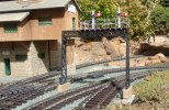
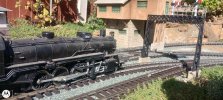
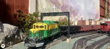
The signals in position and the servos and wiring are barely noticable -
IMG_20260822_120543954_HDR.jpgIMG_20260822_133014680_HDR.jpgIMG_20260921_112258287_HDR.jpgIMG_20260921_112442609_HDR.jpg

The signals work on the bench but now I will have to make a control system. All of the signals on my railway are triggered automatically by the passage of the trains. I seriously considered using an Arduino for these gantry signals, it would be ideal. However I think that an analogue method may survive outside better than a computer based system. I will therefore be using relays and have designed a circuit using Kicad. It will be a project for the coming winter.
 
Last edited:
My semaphore signals have all been working reliably this year but the test will be next year in the spring after the cold and damp winter.

Earlier this year I have been making a pair of gantry signals situated at each end of the main station.
The main gantry was printed in a single piece and I did expect it to be a disaster because it was printed without any supports and it has a lot of unsupported pieces.
I used PETG and it came out not too bad and needed minimal cleaning up to remove whiskers of filament.

I designed the signal using linear servos glued to a base plate with mitred sides. The base then slotted into corresponding guides on the gantry -
View attachment 362860

These linear servos looked a good application because of their tiny dimensions allowing them to fit in the confined space inside the gantry.
However, they were not strong enough to do the job, either just not working or constantly jittering. The open gearing was also vulnerable to tiny specks of debris that totally jammed the mechanism. So it was back to mrcro servos.

Fortunately I was able to adapt the signals without remaking the gantry to use conventional 9g servos. I made a clamp that slotted over the servo and was screwed to the base of the signal post -
View attachment 362861
The mounting tab on the opposite side was cut off and the gap for the servo between the side of the gantry and the mounting post was luckily exactly the correct size.
The servo wires were painted with black liquid tape to hide their bright colours,

Each signal required 4 wires, DC 5+, DC 0 volt and a control wire for each servo.

The 4 wires were run up through the inside of one of the legs, 2 wires per leg and are thus unseen.

They connect at the base to a terminal block that was initially made too close together to tighten the nuts The terminal blocks were printed with a pause at the appropiate height and the M4 nuts were dropped into position before continuing with the print -View attachment 362862

This base has a matching cover that is fixed to the gantry legs and drops over the base acting as weather protection

The wiring at the top of the gantry to the 2 servos and the 2 signal back lights was achieved by making a connector board that is glued to a mitred base that slides into position. The hole is for a clamping screw but the fit of the base was tight enough to not require it-
View attachment 362863

It has 6 pin headers. The four 3 pin headers are for power in and the servos. The two 2 pin headers are for the LED's with a resistor to reduce the power.

Soldered up some brass rod to make the railings -View attachment 362864

The white signal posts were glued into sockets printed with the gantry.
The wires to the lights are routed through a hole inside the posts and emerge out of the sides of the mounting sockets.

The signals in position and the servos and wiring are barely noticable -
View attachment 362865
View attachment 362866View attachment 362867View attachment 362868

The signals work on the bench but now I will have to make a control system. All of the signals on my railway are triggered automatically by the passage of the trains. I seriously considered using an Arduino for these gantry signals, it would be ideal. However I think that an analogue method may survive outside better than a computer based system. I will therefore be using relays and have designed a circuit using Kicad. It will be a project for the coming winter.
unfortunately i can't see attached pictures :(
 
More photos.

The original idea using linear servos -
IMG_20260724_153456031.jpg

Then with the 9g servos and all the wiring -
IMG_20260820_121440315.jpg

Originally made with 4 legged uprights but there was not enough clearance for 2 tracks due to the constraint of printing size. These legs were printed vertically and were designed with U profile sections that make it look very rough. Testing here for clearance.The legs were re-printed as flat 2 - legged uprights-
IMG_20260708_122502059_HDR.jpg

The paired wires coming out of the legs -
IMG_20260724_151837181.jpg

I use enamelled wire for running through the holes in the structure. It comes in various colours and I used red, blue and gold here.
 
My semaphore signals have all been working reliably this year but the test will be next year in the spring after the cold and damp winter.

Earlier this year I have been making a pair of gantry signals situated at each end of the main station.
The main gantry was printed in a single piece and I did expect it to be a disaster because it was printed without any supports and it has a lot of unsupported pieces.
I used PETG and it came out not too bad and needed minimal cleaning up to remove whiskers of filament.

I designed the signal using linear servos glued to a base plate with mitred sides. The base then slotted into corresponding guides on the gantry -
View attachment 363021

These linear servos looked a good application because of their tiny dimensions allowing them to fit in the confined space inside the gantry.
However, they were not strong enough to do the job, either just not working or constantly jittering. The open gearing was also vulnerable to tiny specks of debris that totally jammed the mechanism. So it was back to mrcro servos.

Fortunately I was able to adapt the signals without remaking the gantry to use conventional 9g servos. I made a clamp that slotted over the servo and was screwed to the base of the signal post -
View attachment 363022
The mounting tab on the opposite side was cut off and the gap for the servo between the side of the gantry and the mounting post was luckily exactly the correct size.
The servo wires were painted with black liquid tape to hide their bright colours,

Each signal required 4 wires, DC 5+, DC 0 volt and a control wire for each servo.

The 4 wires were run up through the inside of one of the legs, 2 wires per leg and are thus unseen.

They connect at the base to a terminal block that was initially made too close together to tighten the nuts The terminal blocks were printed with a pause at the appropiate height and the M4 nuts were dropped into position before continuing with the print -
View attachment 363023

This base has a matching cover that is fixed to the gantry legs and drops over the base acting as weather protection

The wiring at the top of the gantry to the 2 servos and the 2 signal back lights was achieved by making a connector board that is glued to a mitred base that slides into position. The hole is for a clamping screw but the fit of the base was tight enough to not require it-
View attachment 363024

It has 6 pin headers. The four 3 pin headers are for power in and the servos. The two 2 pin headers are for the LED's with a resistor to reduce the power.

Soldered up some brass rod to make the railings -
View attachment 363025

The white signal posts were glued into sockets printed with the gantry.
The wires to the lights are routed through a hole inside the posts and emerge out of the sides of the mounting sockets.

The signals in position and the servos and wiring are barely noticable -
View attachment 363026View attachment 363027View attachment 363028View attachment 363029

The signals work on the bench but now I will have to make a control system. All of the signals on my railway are triggered automatically by the passage of the trains. I seriously considered using an Arduino for these gantry signals, it would be ideal. However I think that an analogue method may survive outside better than a computer based system. I will therefore be using relays and have designed a circuit using Kicad. It will be a project for the coming winter.
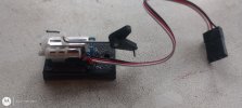
Did you manage to find the Micro Linear Servos with the larger plug as shown, then ones I got had tiny plugs.
 
Back
Top Bottom