3D Semaphore Signals

I'm currently working on a decoder to animate signals - with acceleration in / out plus some bounce. I wont take over this thread but I'll be sure to post something soon. I think it would be spot on for these signals :)
 
AlanL AlanL This project is of great interest to me. I'm currently designing modern signals, but I'd love to be able to print semaphores as well. Yours look great! I shall endeavor to make mine looks half as good in the future.
Thanks, I could send you the files to get you started.

I am also working on motorised signal heads, as apposed to mechanical linkages to a signal box.

AL
 
I'm currently working on a decoder to animate signals - with acceleration in / out plus some bounce. I wont take over this thread but I'll be sure to post something soon. I think it would be spot on for these signals :)
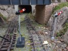
Sounds great, my signals are either on or off, I was just glad that they moved at all :D
 
The next stage of semaphore signals is to have outdoor working versions.

As my railway is US based I have looked at semaphores with 'motorised heads'.

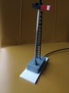
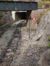
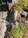
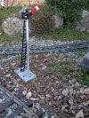
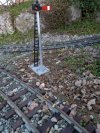
I built and installed the first prototype back in December, pictured here with the posed second prototype in January.
The difference between them is mainly the post diameter, 8mm for the first and 6mm for the second. Using a smaller diameter post allowed more space at the head and I was able to add a drainage/ventilation hole underneath the head.
IMG_20250118_130124825_MF_PORTRAIT.jpg
I tested the first prototype periodically but it had stopped working by the middle of March. There was moisture within the servo.
Version 2 is still working having survived the heavy rains earlier in the year.
IMG_20250124_152515781.jpg IMG_20250124_152551048.jpg
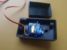
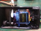
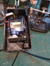
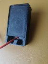
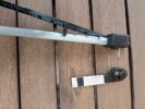
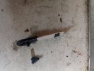
The servo and linkages are fitted inside the top of the base. Then the bottom cover is inserted inside the top and sealed with silicone adhesive. including the cable entry.

IMG_20250123_122216405.jpgIMG_20250114_112241687.jpgIMG_20250112_110926192.jpgIMG_20250123_122050060.jpgIMG_20250123_115535082.jpg
The resistors in the second photo are for the LED light.
The white base was an after thought to help keep it anchored in the ballast. The messy silicone can also be seen.
I intend to make a v3 with some refinements over v2 and see how or if, it survives the next 12 months :coldsweat:

Alan
 
I'm currently working on a decoder to animate signals - with acceleration in / out plus some bounce. I wont take over this thread but I'll be sure to post something soon. I think it would be spot on for these signals :)
This may be of interest re the bounce for the signals

Picaxe is a very versatile microcontroller; I find I am using them a lot lately ever since I found that ChatGPT can write the program in the blink of an eye just as long as you detail what you want it to do.
It is really good for controlling servos to precise positions for use with points and signals.
 
Forgive me if I've put 'two and two together to make four' but I visited the National Garden Railway Show at Stoneleigh last Saturday and came across a lovely little layout tucked away towards the back of the hall - Johnson Harbour. What attracted me were the perfectly proportioned and beautifully made semaphore signals.

AlanL AlanL having read your thread, were these yours? The operator explained they'd been specially made by a member of his club (Northampton?) and kindly removed one to show me the elegantly designed servo mount below. I realise that there may be others who have used the Garden Rail Mag files but these appeared to have been refined exactly as you describe.

If they weren't yours then it looks like you have some competition!
 
You can get waterproof servos, but they will cost a lot more than SG90 clones..

If using outside, I would use a 'cabinet' next to the signal, with the servo in it.. Arm and linkage downwards, so the body of the servo is well above any weather.

I started developing this (with an idea to bring something to market, but there are too many variations to make it viable, really.

PhilP.
 
I'm currently working on a decoder to animate signals - with acceleration in / out plus some bounce. I wont take over this thread but I'll be sure to post something soon. I think it would be spot on for these signals :)
I use the excellent Megapoints System 2 to servo control all my points. Next stage is to add semaphore signals (hence my interest in this thread) - bounce is already programmed in to System 2 as a selectable option on each servo channel. Mine is a loft layout so can't comment on best way to weather-proof them.
 
I use the excellent Megapoints System 2 to servo control all my points. Next stage is to add semaphore signals (hence my interest in this thread) - bounce is already programmed in to System 2 as a selectable option on each servo channel. Mine is a loft layout so can't comment on best way to weather-proof them.
I also have used the Megapoints controllers to do semaphores. They have a really nice semaphore control function in them - I pretty much consider the Megapoints controllers the 'gold standard' for semaphore animation out of all of the semaphore controllers I have tested (which is a fair few now!).

However, the issue with the Megapoints controllers is that, like most other controllers on the market, is that they are 'huge'. Not a problems if you are working inside, however siting these outside either requires waterproof enclosure's local to the points / signals (did that on a temporary basis - boxes not easy to hide!) OR remote to the points / signals (also done that - lots of long distance shielded cabling!).

This is why I have gone down the route of a small decoder (24mm x 40mm), that needs 2 cores to power and send control signals to it, can drive 6 servos or 6 two aspect light signals.

As for servos outside, the SG90 copies I have, haven't lasted that well. The MG90 copies I have (20+) seemed to have lasted well so far - have been outside a year and only 1 has given me issues.
 
Guilty as charged and well spotted at the show.

Alan
Then I add my congratulations to other's. My wife and I did a number of circuits of the traders at the show and, out of the four we found selling signal kits, they were ALL far too big in our opinion - even for 16mm scale.

If you ever decide to sell kits then please do let us all know.

In the meantime, would it be possible to purchase copies of the 3D files from you? I'd be more than happy to pay you (via PayPal perhaps?).

Again, congratulations on producing models that integrated so well with Johnson Harbour - it was a delight.
 
However, the issue with the Megapoints controllers is that, like most other controllers on the market, is that they are 'huge'. Not a problems if you are working inside, however siting these outside either requires waterproof enclosure's local to the points / signals (did that on a temporary basis - boxes not easy to hide!) OR remote to the points / signals (also done that - lots of long distance shielded cabling!).
Yes indeed! I've ended up mounting 8-channel Megapoints boards at all four corners of my layout in 'electrical cabinets' under the baseboards. However, I've just disconnected the CAN-bus cabling in favour of the WiFi networking capability which works a treat.

I know I'm only an indoor modeller but I've often wondered whether the Megapoints boards could be mounted in a weather-proof signal box for outdoor use. After all the prototypes would all have had signal boxes within reasonable proximity of the points and signals they controlled. This then keeps Servo cable runs manageable and, if one boosts home WiFi outdoors, then there's no need for long runs of shielded Can-bus (which incidentally Dave Fenton of Megapoints has tested very successfully). Just a thought.
 
As for servos outside, the SG90 copies I have, haven't lasted that well. The MG90 copies I have (20+) seemed to have lasted well so far - have been outside a year and only 1 has given me issues.

Useful to know, thank you, Alan..

PhilP.
 
Ooops!
Comes from being too hasty..
You never get anywhere, if you are too hasty...
:blush:

PhilP.
 
In the meantime, would it be possible to purchase copies of the 3D files from you?
Thanks for your complements. The lack of choice and the expense encouraged me to design my own semaphores. Helped by the purchase of a 3D printer.

I'm quite happy to send the STL files to you, Send me your email via a PM

Alan
 
As for servos outside, the SG90 copies I have, haven't lasted that well. The MG90 copies I have (20+) seemed to have lasted well so far - have been outside a year and only 1 has given me issues.
Interesting, I thought that the difference was metal gears vs plastic gears. There must be more to the mg90 servos than the gears. Better overall quality perhaps?
The servos that I am using are as cheap as you can find.

Alan
 
Time to update my progress with the outdoor semaphore signal V3. Following on from my post # 24 I have finished and installed the latest version.
The main changes for V3 are the addition of an internal barrier between the blade pivot and the side for the main post. The blade pivot is the only weak spot that would allow rain to enter the signal. With version V2 I added a drainage hole and that seems to have solved the problem of water ingress. Version 3 with the additional barrier will be (hopefully) more weather resistant, if not weatherproof.
I've also had to modify the crank and blade back assembly by shaping the crank as a hook. This was needed to operate over the raised internal barrier as metioned above. The crank has also been made thicker for more strength, the earlier versions were very light on material and looked fragile.
Whilst working on this V3 design the V2 version has stopped working mechanically although the servo is still working. I havent had the chance to inspect the cause of V2 failing but I suspect that it may be related to the constant sunshine of recent weeks. The V2 signal was made using PLA filament which is liable to wilt in the heat.
With that in mind I've built the V3 using PETG for the crank assembly.

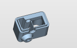
3D images of the relevent parts
Housing.pngCrank Assembly.png

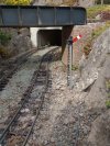
Signal in position
IMG_20250520_164859406.jpg
IMG_20250520_164854038.jpg

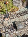
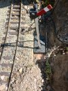
The signal here is slightly remote from any buildings for protection and is therefore self-contained. It gets it's power from the track and also the yellow wire to activate the signal. The control electronics are contained within the waterproof enclosure that was used for the V1 version.
IMG_20250520_111119749_HDR (1).jpg

Wires connected and the signal base is to be buried
IMG_20250520_112714581_HDR.jpg

The enclosure is also buried nearby and as it survived with the V1 version it should be okay. Cable entry is through stretchy membranes that seal the cables.
IMG_20250520_112805420_HDR.jpg

Now I need Lots of rain and lots of hot sunshine to see if it survives :D :D

I will replace the V2 signal (as it has stopped working) and improve the blade and lens area. At the moment there is no detail on the blade, the lens area can be improved and the assembly was tricky to align all the parts.

Alan
 
Update on the failed V2 signal.
I had forgotten that I had used a brass rod for the blade pivot.

The operating crank inside the signal head and the signal blade were both super glued to the brass rod. The crank part was cut away to allow space for the super glue to hold but the blade was just a plain hole. The problem with a plain hole is that any glue is pushed away as the parts are assembled.
I will repair this signal again with super glue but this time I will grind a flat or 2 flats on the rod to provide a surface for the glue to attatch to.

The V3 version was made with all these components printed as 1 assembly and will not fail in this way (I hope :( :( :( )

IMG_20250531_165045760_HDR.jpgIMG_20250531_165327810.jpg

Alan
 
Back
Top Bottom