Understanding my voltmeter ...

RH Prague

Central European. the station pub is Czech !!
28 Oct 2009
396
20
Prague
Best answers
0
Country flag
I've frequently confessed my illiteracy on the electronics side of our hobby, and that my brother-in-law fortunately is an electrician and happy to help keep things ticking over. He bought me a voltmeter for Christmas, bless him, but the results have been puzzling me since I got it. He was here yesterday and is equally puzzled (but freely admits it might be a 'digital; thing, which he understands less well.)

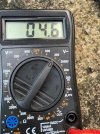
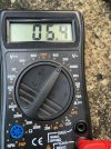
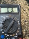
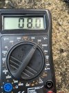
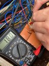
Basically when testing the track for power the meter readings just jump around and certainly hardly ever reach 18v. See the first 4 photos, which is from the same test. He's sure the meter is OK, he tested it on a battery, and then as the fifth photo shows tested it on the switch box which is powered from the LGB transformer and not the Massoth central station. Solid 18v every time.

So what's going on here on the track? The actual performance on the tracks is generally fine, we fixed a little niggle with one point yesterday but otherwise every loco is happy - but you wouldn't expect it from those meter readings...
 

Attachments

  • IMG_1442.jpeg
    IMG_1442.jpeg
    91.2 KB · Views: 0
  • IMG_1443.jpeg
    IMG_1443.jpeg
    87.8 KB · Views: 0
  • IMG_1444.jpeg
    IMG_1444.jpeg
    88.8 KB · Views: 0
  • IMG_1445.jpeg
    IMG_1445.jpeg
    91.2 KB · Views: 0
  • IMG_1446.jpeg
    IMG_1446.jpeg
    83.1 KB · Views: 0

PhilP

G Scale, 7/8th's, Electronics
5 Jun 2013
33,592
3,525
Nottingham
Best answers
0
Country flag
You are comparing apples and oranges..

The meter, although on an 'AC' range, can obviously not cope with the higher frequency (and squarer-wave) signal / voltage on your track. - You could also be making a very poor connection, but I doubt this, as you are getting incorrect, but consistent results.

There are meters made, which will give a true reading of the voltage given out by your central station, but the niche market makes these a little expensive, unless you 'need' to know true results. - Testing and diagnosing faults at a 'professional' level.

A work-around, is to use a 50V (or higher) rated diode, in series with one of your meter-leads, and measure the half-wave DC.
This will give you a 'something to compare to' reading, at different points around your track. Useful for finding bad joints, but only if you have a load on the track, so a decent amount of current is flowing. - Your electrician friend, can explain why you don't see the fault, under no-load conditions..

You 'see' the correct voltage at the switch-box, as this is low-voltage AC, at the standard frequency of 50Hz.

PhilP
 

Gizzy

A gentleman, a scholar, and a railway modeller....
26 Oct 2009
36,152
2,278
63
Cambridgeshire
www.gscalecentral.net
Best answers
0
Country flag
I agree with Phil.

The output from your Massoth is a high frequency signal and not a regular 50 Hz RMS voltage which is what your DMM is set to measure....
 

RH Prague

Central European. the station pub is Czech !!
28 Oct 2009
396
20
Prague
Best answers
0
Country flag
I agree with Phil.

The output from your Massoth is a high frequency signal and not a regular 50 Hz RMS voltage which is what your DMM is set to measure....
Ok, thanks both, I think I've grasped why it doesn't work. Explaining the work around might be a challenge though, as I have to do it in Czech :( Fortunately at this stage it's something "nice to have" rather than need to have, but it's going to be useful in future, as most of the track has been in place 14 years now.
 

Rhinochugger

Retired Oik
27 Oct 2009
36,772
4,243
North West Norfolk
Best answers
0
Country flag
My favourite test unit for track power is an 18v motor with leads.

If I'm searching for a fault or low voltage (which, of course, rarely happens on my railroad :giggle::giggle::giggle: ) I switch the power controller up to 3/4 power and take the motor round the track, lay it between the rails (no, it doesn't touch 'em) and then hold one lead to each rail. If the motor jumps healthily when the power is applied, things are OK :nerd::nerd::nerd:

That is the extent of my electrical knowledge :emo::emo::emo::emo::emo:
 

dunnyrail

DOGS, Garden Railways, Steam Trains, Jive Dancing,
Staff member
GSC Moderator
25 Oct 2009
26,206
4,997
75
St.Neots Cambridgeshire UK
Best answers
0
Country flag
My favourite test unit for track power is an 18v motor with leads.

If I'm searching for a fault or low voltage (which, of course, rarely happens on my railroad :giggle::giggle::giggle: ) I switch the power controller up to 3/4 power and take the motor round the track, lay it between the rails (no, it doesn't touch 'em) and then hold one lead to each rail. If the motor jumps healthily when the power is applied, things are OK :nerd::nerd::nerd:

That is the extent of my electrical knowledge :emo::emo::emo::emo::emo:
A buzzer will do the same thing even with DCC though the life will not be long if you leave it attached for a long time.
 

Rhinochugger

Retired Oik
27 Oct 2009
36,772
4,243
North West Norfolk
Best answers
0
Country flag
A buzzer will do the same thing even with DCC though the life will not be long if you leave it attached for a long time.
It doesn't jump quite the same :shake::shake::shake:

The 18v motor kicks quite impressively :):):)
 
8 Mar 2014
7,806
972
San Diego
Country
Armenia
www.elmassian.com
Best answers
0
Country flag
There's a couple of things here, I'll break them into separate pieces.

First, the ability to accurately measure DCC voltage (which is not your problem)
Most inexpensive meters do not measure "RMS" AC, and use an approximation (via an electrical circuit) to measure the 50 Hz sine wave AC you have.
Your DCC signal is a square wave, and the approximation does not always give an accurate voltage.
If you do not have an RMS AC meter (which I can see you do not), then get a full wave bridge rectifier. it has 4 wires, One will show +, one will show -, hook these to your meter on DC.
The other 2 wires have the Tilde "~" and notice it is the symbol for AC (alternating current) on your meter. hook these 2 wires to the rails.
The full wave bridge will convert the DCC to DC to be read accurately.

OK, but that is not your problem. Ideally the voltage on the rails is constant around the layout. Every connection between the command station output has some resistance. Those resistances "eat" voltage, and the amount they "eat" is dependent on the resistance AND the current flowing.

These losses are called "voltage drops" (makes sense, your voltage "drops" at each one of these connections. How much voltage is dropped/lost is dependent on the quality of the connection.

But in order to compare the voltage before and after a rail joint, for example, you need a CONSISTENT and STEADY load on the track. No load, no current flows. You can prove this to yourself by disconnecting everything from the track (anything powered by the rails, including switch motor decoders). Then the voltage measured everywhere will be virtually the same.

This is because virtually no current is being drawn other than a minuscule amount for the meter, and with very little current, the resistance does not make much difference:

V = IR, the Voltage lost is equal to the current drawn (I) and the resistance (R)

From your basic algebra if either I or R are very small then the Voltage "lost" is very little. So the full voltage can get pretty much anywhere.

Now you add a loco, and now you are drawing current. All those little bits of resistance will be "voltage drops", and to make it worse the motor is constantly varying the current it is using.

Your meter SHOULD bounce around everywhere in it's readings, and you will notice that the voltage on the rails gets lower the further you are from the feed point.

That is the simplified answer to your question of what is going on. Since most people have their track in a loop, this can further complicate readings since voltage can come from both directions, think of it like a clock, you feed the power at 12 o'clock, and the loco is at 4 o'clock. There are TWO paths the voltage can take. If you are trying to find a problem, you have to "break the circle" to find the bad connections faster.

By the way, the best load to find voltage drops is not a motor, but a large resistor or constant load. I have an 8 amp load for this purpose.

read this page: Electrical troubleshooting

resistor_.JPG


Greg