funandtrains
Registered

Heyn produce an R1 Y point but the price is very expensive then you have to get it from Germany.


Yeah, I found it this afternoon, I'm just wondering how it would integrate into my railway, with the metal frogs etc. There's also no pictures....Heyn produce an R1 Y point but the price is very expensive then you have to get it from Germany.
I assume it is similar to the R0 and R2 versions. You would have to use insulated rail joiners on the inner rail ends as the whole frog changes polarity.Yeah, I found it this afternoon, I'm just wondering how it would integrate into my railway, with the metal frogs etc. There's also no pictures....

But only if you wire it up to a switch?I assume it is similar to the R0 and R2 versions. You would have to use insulated rail joiners on the inner rail ends as the whole frog changes polarity.
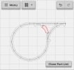
It says to use their switch on the website.But only if you wire it up to a switch?
PhilP.
Hmmmmm. Brut force.....Well, that would probably be the cheapest solution!
Can you borrow a railbender to get the curve smooth? The better it is done, the less running problems you're likely to have.
Jon.

Not sure about how the frog works, but as you are using EPL motors, use if the electrical switch and isolations either side of the frog will allow it to be non shorting when changed.In fact looking at the points from Heyn, they appear to do a R1 Y. But the frogs looks different, as in all brass. Are Heyn points designed for non track power, as they would surely cause a short circuit?


Can you just use the rail bender in the middle of a longer piece of track, and just cut off the ends to suit?Problem with a rail bender produced solution is that most benders do not bend the rail to the very end, you might have a small staight transition at each end. Then you have to produce a decent transtional curve in between in a very small section, will it work geometrically and not cause derailments ? You are looking at all up around £200 for an Xmas neighbour pleasing feature. That's your choice, I have committed far worse extravagances I will admit. Like the whole garden railway. I look forward to seeing the results and smiles on all the kids faces


You could but it is an added bit of faff. What is of greater concern is the geometry you will end up with given the even tighter curvature required with the angement that dipenses with a proper Y point at those radii. Gérard also makes a point about possible conflicts by introducing a circle within an already small polarity controlled reversing loop when entering and leaving. That one is messing with my mindCan you just use the rail bender in the middle of a longer piece of track, and just cut off the ends to suit?
 Although if the whole train remains within the loop after entering then that should not conflict and as it exits likewise. Where are the polarity reversing triggers ?


I don’t see anything here mentioning that this is a turnaround loop.

Hm it is as creating the loop will make the entrance/exit to the loop shorter thus meaning possible problems with some if the longer trains run, never thought of that myself well spotted @GerardBecause it is NOT relevant to the question.....