You are using an out of date browser. It may not display this or other websites correctly.
You should upgrade or use an alternative browser.
You should upgrade or use an alternative browser.
More Regner Else and no water
- Thread starter Fred2179G
- Start date
Fred2179G
Registered
It is definitely the timing. When I compared the sides, the piston on the valve on the left was moving further in and out than the one on the left. So I moved the thingamijig on the wheel to cut down the travel. I guess that's where the 1.5mm+1.5mm come in. I also ran a test and moved the sliding bracket while it was running - yes, I got it to run on rollers, though not smoothly yet.Unless you found out already this is not the cause for jamming.
All the steam leaks seem to be gone, including the stuffing box on the oiler adjuster, which I seem to have broken off the adjust nut when tightening it. A large teflon loop seems to have solved it.
So today's project is to print and translate those Emma instructions about setting the timing, and to find my mm ruler. . . Interesting that the photos in the manual show the piston valve sticking out the front of the valve chest.
Fred2179G
Registered
Well, running low on butane so there won't be many more tests until I get to the Asian market. But some progress today.
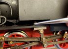
Here's my attempts to put the bolt back in the bracket. It came out when I was experimenting yesterday.
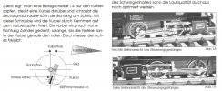
Then the process of timing was undertaken. Here's the translated important bit:
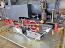
"To adjust the control piston, turn the slide rod pivot point of the crank at bottom dead center. The rocker should be almost vertical. Now loosen the fastening screws of the swingarm holder and moves it until the control piston is flush with the cylinder at the front. Now you have the center."
Here's a pic with arrows:
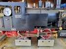
And away we went to fire up again. No actual complete revolutions - the wheels stopped in the same position every time. Here's the left and right sides when it stops/jams. The right side is at full extension:
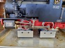
The left side is centered, at maximum power stroke position.
My only deduction so far is that I am not getting steam on the left. This is corroborated by the fact that water leaks out when it is warming up from the right side cylinder+valve piston, but not from the left.
Any thoughts, anyone?
Edit after thinking:
The fact that the wheels do almost a full revolution before stopping suggests that the left side cylinder is getting steam behind one side of the piston, but not the other. As the valve's job is to open the steam inlet at one end and the exhaust at the other, it could be that the valve isn't letting steam in or out in one position. So the valve isn't centered and doesn't move enough one way.
Here's my attempts to put the bolt back in the bracket. It came out when I was experimenting yesterday.

Then the process of timing was undertaken. Here's the translated important bit:
"To adjust the control piston, turn the slide rod pivot point of the crank at bottom dead center. The rocker should be almost vertical. Now loosen the fastening screws of the swingarm holder and moves it until the control piston is flush with the cylinder at the front. Now you have the center."
Here's a pic with arrows:

And away we went to fire up again. No actual complete revolutions - the wheels stopped in the same position every time. Here's the left and right sides when it stops/jams. The right side is at full extension:

The left side is centered, at maximum power stroke position.

My only deduction so far is that I am not getting steam on the left. This is corroborated by the fact that water leaks out when it is warming up from the right side cylinder+valve piston, but not from the left.
Any thoughts, anyone?
Edit after thinking:
The fact that the wheels do almost a full revolution before stopping suggests that the left side cylinder is getting steam behind one side of the piston, but not the other. As the valve's job is to open the steam inlet at one end and the exhaust at the other, it could be that the valve isn't letting steam in or out in one position. So the valve isn't centered and doesn't move enough one way.
Last edited:
ol_hogger
Registered
Do yourself a favor and take the cab off for better acess.
No need to actually measure the mm of valve travel. Center position, i.e. flush wirh front of steam chest must be reached in wheel and crank position described which is piston's rear dead point.
Even in German language Regner's wording is not as straightforward as it could be wished for.
No need to actually measure the mm of valve travel. Center position, i.e. flush wirh front of steam chest must be reached in wheel and crank position described which is piston's rear dead point.
Even in German language Regner's wording is not as straightforward as it could be wished for.
Last edited:
Fred2179G
Registered
Actually, I am so deep in to it that I can tell your loco hasn't been run. You're missing the blank on the end of the manifold (2nd pic) and on the same pic it looks as if your crank isn't in the right place - it should be just to the side of the axle; or to put it another way, you should see the axle end:Pictures of my loco should give you a rough idea if it helps.
"The crank is forward turned towards the cylinder until the rear edge the crank just the full diameter of the axle is seen"
Yours looks to be covering the axle, but that could just be the angle of the photo.
That thought occurred to me, but I'm not having too many problems with it - though I think I over-tightened one of the bracket screws and probably broke it; that's the problem with M2 brass bolts. I have lots more. Regner's little M2/M3 spanner works.Do yourself a favor and take the cab off for better access.
I had about 4 tests yesterday. First with the valve gear exactly as the manual says, and as you also describe. Then I double checked the crank position on the rear wheel and adjusted both to make sure I was getting some valve movement. (2nd test.) Then I experimented with the left side, moving the bracket slightly forward (3rd) and backward (4th test.)Center position, i.e. flush with front of steam chest must be reached in wheel and crank position described which is piston's rear dead point.
I got the same results. There is willingness to rotate, but only through almost 1 revolution. Then it stops. With 2 bar on the gauge, it whips rapidly to the 'stop' position!
This was made from a kit. (Were they all sold as kits, I wonder?) I've had to put teflon on 2 of the fittings on the manifold which leaked, and on the oiler aduster, which leaked badly at the stuffing.
All this suggests the builder never tried to run it. And that leads to the other possibility that there is something wrong in the steam passages. Maybe one is blocked. I wonder, if I removed a piston, if I could tell if steam was getting to both ends at the right time? Or maybe unbolt the valve rod and move it manually to demonstrate that it works in directing the steam to the piston?
I really don't want to un-build this little beast.
Last edited:
Fred2179G
Registered
Hmmm . . I'll have to take a look at that, when I figure out what they are.Check the whatchacallit cylinder glands. They might foul the crosshead.
Fred2179G
Registered
Well, after 2 boilers of water during testing, I figured it was time for some more steam oil, and (of course) there was no oil as the drain screw has no sealing washer. I suspect the steam pressure pushed all the oil out. I reset the screw with an o-ring on it.oiler aduster, which leaked badly at the stuffing
A quick test after I double checked everything was perfectly aligned. I waited until it had 3 bar before opening the throttle. Some oil fizz and spatter so the oiler is now working. But no continuous revolutions at the wheels.
Time to get my air pump out and set it up to run on air. Much easier to adjust if it isn't hot!
Thanks must look into that, as I said before I like it so much never been run!Actually, I am so deep in to it that I can tell your loco hasn't been run. You're missing the blank on the end of the manifold (2nd pic) and on the same pic it looks as if your crank isn't in the right place - it should be just to the side of the axle; or to put it another way, you should see the axle end:
"The crank is forward turned towards the cylinder until the rear edge the crank just the full diameter of the axle is seen"
Yours looks to be covering the axle, but that could just be the angle of the photo.
That thought occurred to me, but I'm not having too many problems with it - though I think I over-tightened one of the bracket screws and probably broke it; that's the problem with M2 brass bolts. I have lots more. Regner's little M2/M3 spanner works.
I had about 4 tests yesterday. First with the valve gear exactly as the manual says, and as you also describe. Then I double checked the crank position on the rear wheel and adjusted both to make sure I was getting some valve movement. (2nd test.) Then I experimented with the left side, moving the bracket slightly forward (3rd) and backward (4th test.)
I got the same results. There is willingness to rotate, but only through almost 1 revolution. Then it stops. With 2 bar on the gauge, it whips rapidly to the 'stop' position!
This was made from a kit. (Were they all sold as kits, I wonder?) I've had to put teflon on 2 of the fittings on the manifold which leaked, and on the oiler aduster, which leaked badly at the stuffing.
All this suggests the builder never tried to run it. And that leads to the other possibility that there is something wrong in the steam passages. Maybe one is blocked. I wonder, if I removed a piston, if I could tell if steam was getting to both ends at the right time? Or maybe unbolt the valve rod and move it manually to demonstrate that it works in directing the steam to the piston?
I really don't want to un-build this little beast.
Fred2179G
Registered
ol_hogger
Registered
"Cylinder gland" maybe
piston rod packing
is the proper term.
Last edited:
Fred2179G
Registered
I think the nut on the piston rod where it hits the end of the cylinder face is the gland nut, so you were in the ballpark.piston rod packing
Unfortunately it doesn't interfere. The stopping isn't consistently in the same place, which is why I'm thinking a blocked steam pipe? When I get my air pump rigged, I'll propably remove the valve bracket pins and move them manually, to prove they are working.
Jake, the seller, confirms he had the same problems - so it isn't just me!
Fred2179G
Registered
Afraid not. The attempt of the wheels to move is reversed when you rotate the valve. The instructions say 45 deg forward or 45 deg backward. Those earlier photos (p.1) of other poeple's locos show the position.the reversing valve in the wrong position
I did some more translation of the Emma manual, and found this gem just after the description of installing the reversing valve:
"The reversing valve later has the task of continuously controlling the speed and direction of the locomotive. This can be done by hand with a pull rod or later with a radio remote control." Pull rod? What pull rod? There isn't one in the parts list of the Emma or in the pictures.
Ah well, onward and upward. . . I got my air compressor out of the car, did the car tires/tyres and brought it in to the bench. A small 12V battery was needed to power it, and fortunately this one came with a bunch of little adaptors for pumping up balls, pool toys, etc. One was just perfect for the safety valve hole:
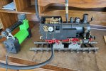
I can get about 2-3 bar without any strain. You'll notice the valve rod is already removed and available for testing.
In the instructions, there is a lengthy section about winding a teflon string around the piston to make it seal, and also putting a teflon string in the gland to seal the end of the piston.
The valve rod inside the cylinder also has a couple of slots in it, which might be for sealing rings of teflon. It is clear that the air pressure is trying to move the wheels, but not very much.
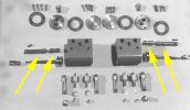
Of course, there is no teflon in there now, nor any sign of any having been put in. After a long description of how to wind teflon on a piston, and how to put it in the cylinder with the ends bolted on, there is this cryptic bit:
"The control piston 4 is now carefully inserted into the overlying cylinder bore, the so-called control bore. The control piston must be able to be moved easily and quickly, but without play. It should also be mentioned that it has to be oiled beforehand."
No mention of putting anything on the valve to seal it in the cylinder's valve shaft. Well, it shouldn't be difficult to do a bit of teflon sealing now I have it loose.
ol_hogger
Registered
The grooves your arrows point to are the steam channels for the outer admission, i.e. guiding the steam to the port at the respective end of the cylinder. The other port is opened by the wider groove between, while the thicker sections separate live steam from exhaust appropriately.
I am afraid this is no clearer than Regner, in short: no teflon here! - rather this is where to look for obstacles, such as stray teflon. I think Wilesco have a video of the priciple on their website, they usethe same a very similar type of this time honored sort of valves. - I was in error here, Wilesco use slip excentrics and their valves are even simpler.
(It is the piston groove which has to be filled with teflon - a possible source for the stray piece I suspect)
I am afraid this is no clearer than Regner, in short: no teflon here! - rather this is where to look for obstacles, such as stray teflon. I think Wilesco have a video of the priciple on their website, they use
(It is the piston groove which has to be filled with teflon - a possible source for the stray piece I suspect)
Last edited:
This thread is becoming a wonderful saga of how and what to do with a Regner, so much learning available within the words. I sincerely hope that the recalcitrant loco is eventually sorted. Certainly it will not be for the want of trying.
Fred2179G
Registered
You can say that again. I refuse to let inanimate steam engines defeat me!Certainly it will not be for the want of trying.
Fred2179G
Registered
I was puzzling how it worked if the only steam channel was the wide middle section.The grooves your arrows point to are the steam channels for the outer admission, i.e. guiding the steam to the port at the respective end of the cylinder. The other port is opened by the wider groove between, while the thicker sections separate live steam from exhaust appropriately.
So no sealing at all in the valve area. Hmm . . I wonder how I test each channel individually.


