Is this real?

Gerard

Co-Author " Our Model Garden Railway" on Amazon
Country flag
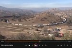
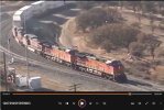
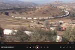
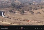
I found an old film footage on my PC. Helas I do not remember how I got it, but its an insane long train with 4 diesel locos at the front running in a circle to a higher level. Does anyone reckognise this place in the USA?
I tried to upload the movie but that did not work. Can anybody explain how to upload a movie?
 

Attachments

  • Long train USA 1.jpg
    Long train USA 1.jpg
    116.3 KB · Views: 19
  • Long train USA 2.jpg
    Long train USA 2.jpg
    142.7 KB · Views: 21
  • Long train USA 3.jpg
    Long train USA 3.jpg
    139.1 KB · Views: 18
  • Long train USA 0.jpg
    Long train USA 0.jpg
    124.7 KB · Views: 19
I found an old film footage on my PC. Helas I do not remember how I got it, but its an insane long train with 4 diesel locos at the front running in a circle to a higher level. Does anyone reckognise this place in the USA?
I tried to upload the movie but that did not work. Can anybody explain how to upload a movie?
Google Lens is my friend. Am I really up at this hour ? :giggle:

 
Yes, I recall watching that clip years ago - very possibly posted here by someone on this forum!

It's certainly real....

Jon.
 
What I find fascinating about this situation is that the 4 locos can generate sufficient pulling force to overcome the friction resistance of hundreds of flanges of the steel wheels that are pulled sidewards to the side of the track. I guess these trains have double axis wheels at the front and rear of each car, so the wheels are parallel to the track. Yet the first cars have to transfer the total pulling force to the next car while that force has to make a small deviation angle. I wonder this situation can be modelled on G-scale? The question is whether the friction forces in the G-scale model are reproduced with the same scale factor as the weight of the train? I remember from mechanics that the friction angle between two surfaces depends on the actual normal force between both sides. It is larger at lower normal forces. So you probably need relatively more pulling power in the model? Has anybody looked into this problem before?
 
Some things don't scale.
We also don't tend to move more than fresh-air in our rolling stock, so our trains never do the work a real locomotive has to do.

There again, our curves are ridiculous! Adding to problems with friction and drag.

PhilP.
 
What I find fascinating about this situation is that the 4 locos can generate sufficient pulling force to overcome the friction resistance of hundreds of flanges of the steel wheels that are pulled sidewards to the side of the track. I guess these trains have double axis wheels at the front and rear of each car, so the wheels are parallel to the track. Yet the first cars have to transfer the total pulling force to the next car while that force has to make a small deviation angle. I wonder this situation can be modelled on G-scale? The question is whether the friction forces in the G-scale model are reproduced with the same scale factor as the weight of the train? I remember from mechanics that the friction angle between two surfaces depends on the actual normal force between both sides. It is larger at lower normal forces. So you probably need relatively more pulling power in the model? Has anybody looked into this problem before?
Well, the curvature in that film is actually fairly big and the greatest load is likely to be the dead weight.

When it comes to railway wheels in the 1:1 world, they are designed to reduce friction in a number of ways - that is the main advantage of the 'iron way'.

The larger the diameter of the wheel, the less friction in the axle boxes, and then remember that the flanges do not guide the wheels, the tapered wheel profile does that. The flanges only come into play where there are check rails at points and on very tight curves.

Are there any helper locos further down the train?
 
Well, the curvature in that film is actually fairly big and the greatest load is likely to be the dead weight.

When it comes to railway wheels in the 1:1 world, they are designed to reduce friction in a number of ways - that is the main advantage of the 'iron way'.

The larger the diameter of the wheel, the less friction in the axle boxes, and then remember that the flanges do not guide the wheels, the tapered wheel profile does that. The flanges only come into play where there are check rails at points and on very tight curves.

Are there any helper locos further down the train?
Almost certainly there are mid-train helpers and pushers at the tail end, both to add power and to ease the strain on the couplers.
 
Think I saw a vid of a derailment there last year - I bet that was fun to put right.
 
I checked the movie but there are no more locos.
Rhino chugger you are right about the tapered wheel profile. During my study at Delft University there was a student who had made a model of a moving train calculating the frequency of the left en right movement caused by this profile. If I remember well there was an issue with the frequency of this movement depending of the combination of the speed of the train, the angle of the profile , and the load on the wheels.
With little or no damping the system could become unstable when it reached the resonant frequency.
 
Talking about the profile of the wheels, once a wheel is off side of the rail center position the than a lttle bit larger radius of the most outer wheel causes that wheel to steer back to the middle and vice versa when the other wheel reaches the off side position. I wonder if this mechanism gets the wheel nice and smooth in its optimal central position. Interesting train mechanics problem!
 
What I find fascinating about this situation is that the 4 locos can generate sufficient pulling force to overcome the friction resistance of hundreds of flanges of the steel wheels that are pulled sidewards to the side of the track.
Typically, they cannot do so. Trains on this line would invariably have multiple Radio Controlled DPU's (Diesel Pusher Units) inserted into the train to release the strain on the couplers and relieves the lead units of the full weight of the train, making it easier to move on grades. Typically, consists of the lead locomotives on the head end, "swing" (mid-train) helpers, and pusher locomotive(s) on the rear.

Your video maybe the odd man out with no DPU's due to being a short, lightweight train easily managed with only four lead units? Unfortunately the video's URL has not been provided for us to verify.

The DPU's also provide regenerative braking for downhill runs which would easily surpass the braking capability of just the leading locomotives should they have been alone.

This video shows short formation trains like your photos with no DPU's and longer, heavier trains with inset DPU's and Tail DPU's (Helpers).
 
Last edited:
I checked the movie but there are no more locos.
Rhino chugger you are right about the tapered wheel profile. During my study at Delft University there was a student who had made a model of a moving train calculating the frequency of the left en right movement caused by this profile. If I remember well there was an issue with the frequency of this movement depending of the combination of the speed of the train, the angle of the profile , and the load on the wheels.
With little or no damping the system could become unstable when it reached the resonant frequency.
A director of the Ffestiniog Railway attended our local model show with a length of model railway track, and an axle with, what was effectively, two half barrels each end. He proceeded to run it up and down the track without it falling off :clap:

Slower railways with tighter curves, like our Docklands Light Railway, have wheels with greater angles on the tread profile, but such profiles would cause too much hunting (oscillation) on higher speed trains.
 
Back
Top Bottom