
David1226
Registered

Part 1 of 2
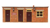
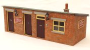
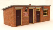
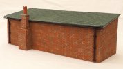
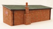
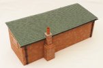
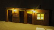
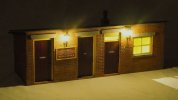
With one exception, all of the buildings on the Claptowte Railway are constructed from resin cast kits, the majority by Kippo Models. All have been kit bashed to a greater of lesser degree, with extra detail and lighting added. For my last project involving resin cast kits, I had the urge to combine two kits, to make a single building. To that end, some time ago, I purchased two Kippo Models resin cast kits, before they went over to producing their buildings in 3D printed plastic.
The buildings were both trackside structures with sloping tiled roofs. Each had a different facade, one with double doors, and no windows, the other with a single door and a single window. I wanted to combine the two kits to build a goods office for Goudes Sidings, on the Claptowte Railway. With these kits, the wall ends have staggered brick courses, which mesh together at the corners. Once the four wall are glued together, any protrusions have to be filed down, and any gaps filled. The brick courses then need to be re-scribed, at the corners, so that everything blends in. Combining two kits, meant that two end walls were surplus to requirement and could be discarded. It also means that where the two rear walls and the two front walls join, you now have two ‘male’ ends, which cannot be joined without alteration.
The first pic shows the cleaned up components, illustrating to wall joints in need of modification. Neither kit comes with gutting or drainpipes. When I ordered 3D printed guttering and drainpipes, to use on the recently completed scratch built Santa’s Grotto carriage shed, at the same time, in anticipation, I also order guttering and drainpipes for this build.
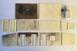
After all of the resin cast components had been cleaned up with files and sandpaper, the first job was to alter the wall ends to convert one of each into a ‘female’ end, in order that the two walls can be meshed together, to form a joint.
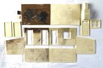
The first step was to glue together the two halves of the rear wall and the two halves of the rear wall, making every effort to keep everything as straight as possible. I used superglue to glue everything, so there wasn’t much time to line everything up. The inside edges of the joints were reinforced by gluing strips of thin plywood, along the joints. Once this had been done, the four walls were glued together in the normal way, interlocking the brick courses at each corner. Any protruding bricks were then filed down and any gaps filled. I used domestic quick drying Polyfilla rubbed into the joints, then once dry, the brick courses were re-scribed.
The two halves of the roof had their ends squared up and were then glued together with a butt joint. This joint was similarly reinforced by gluing a piece of thin plywood to the underside of the join. As with the brickwork, any gaps in the joint had Polyfilla rubbed in, and when dry, the tiles were re-scribed. I over sprayed the area of the join with plastic primer, to show up any blemishes. This process was repeated until I was happy that the join was not immediately obvious.
The two halves of the tiled roof, joined together.
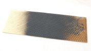
The shortening of the combined lengths of the buildings, plus a redundant overhang at the joined ends, meant that the roof was now too long and had to be cut to the appropriate length, once it could be offered up to the assembled walls. Also a notch had to be cut in the rear, to fit around the chimney stack.
The assembled shell of the building.
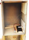
A 3mm plywood dividing wall was added between the two halves of the building, to provide extra strength and rigidity, as well as for cosmetic reasons.
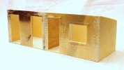
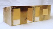

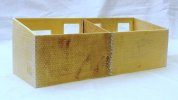
The walls, roof and chimney stack shown primed and assembled, but at this stage not glued together, that would be done after painting.
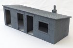
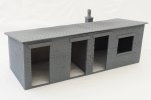
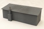
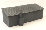
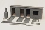
The picture below shows all of the component parts primed and ready for painting, prior to assembly. Additional parts, not included, as already mentioned, the guttering and drainpipes. There were two lengths of guttering, one had to be cut short, to fit around the chimney stack, the remainder of that was cut to length and glued to the second piece to fit on the opposite side of the chimney. The drainpipes were straight and would not fit. I overcame this by softening the end in boiling water, then bending a neck in it, to meet up with the guttering. I also cut and shaped two soffit boards, from plasticard, to go on the two end walls.
The only other modifications to the parts, as purchased, were as follows: Concrete lintels were added above the two doors on the left. These were from 1.5mm pasticard, to cover the wooden lintels, on that side, and to match the lintels on the other half of the building. The other alteration was to drill ventilation holes into the top of the centre door, which was destined to become the W.C. I felt that this would have been in keeping with the period, and it was well known that things could get a bit whiffy after ‘Jones the Steam’ had been in there and ‘dropped his ash pan’.
David
With one exception, all of the buildings on the Claptowte Railway are constructed from resin cast kits, the majority by Kippo Models. All have been kit bashed to a greater of lesser degree, with extra detail and lighting added. For my last project involving resin cast kits, I had the urge to combine two kits, to make a single building. To that end, some time ago, I purchased two Kippo Models resin cast kits, before they went over to producing their buildings in 3D printed plastic.
The buildings were both trackside structures with sloping tiled roofs. Each had a different facade, one with double doors, and no windows, the other with a single door and a single window. I wanted to combine the two kits to build a goods office for Goudes Sidings, on the Claptowte Railway. With these kits, the wall ends have staggered brick courses, which mesh together at the corners. Once the four wall are glued together, any protrusions have to be filed down, and any gaps filled. The brick courses then need to be re-scribed, at the corners, so that everything blends in. Combining two kits, meant that two end walls were surplus to requirement and could be discarded. It also means that where the two rear walls and the two front walls join, you now have two ‘male’ ends, which cannot be joined without alteration.
The first pic shows the cleaned up components, illustrating to wall joints in need of modification. Neither kit comes with gutting or drainpipes. When I ordered 3D printed guttering and drainpipes, to use on the recently completed scratch built Santa’s Grotto carriage shed, at the same time, in anticipation, I also order guttering and drainpipes for this build.
After all of the resin cast components had been cleaned up with files and sandpaper, the first job was to alter the wall ends to convert one of each into a ‘female’ end, in order that the two walls can be meshed together, to form a joint.
The first step was to glue together the two halves of the rear wall and the two halves of the rear wall, making every effort to keep everything as straight as possible. I used superglue to glue everything, so there wasn’t much time to line everything up. The inside edges of the joints were reinforced by gluing strips of thin plywood, along the joints. Once this had been done, the four walls were glued together in the normal way, interlocking the brick courses at each corner. Any protruding bricks were then filed down and any gaps filled. I used domestic quick drying Polyfilla rubbed into the joints, then once dry, the brick courses were re-scribed.
The two halves of the roof had their ends squared up and were then glued together with a butt joint. This joint was similarly reinforced by gluing a piece of thin plywood to the underside of the join. As with the brickwork, any gaps in the joint had Polyfilla rubbed in, and when dry, the tiles were re-scribed. I over sprayed the area of the join with plastic primer, to show up any blemishes. This process was repeated until I was happy that the join was not immediately obvious.
The two halves of the tiled roof, joined together.
The shortening of the combined lengths of the buildings, plus a redundant overhang at the joined ends, meant that the roof was now too long and had to be cut to the appropriate length, once it could be offered up to the assembled walls. Also a notch had to be cut in the rear, to fit around the chimney stack.
The assembled shell of the building.
A 3mm plywood dividing wall was added between the two halves of the building, to provide extra strength and rigidity, as well as for cosmetic reasons.
The walls, roof and chimney stack shown primed and assembled, but at this stage not glued together, that would be done after painting.
The picture below shows all of the component parts primed and ready for painting, prior to assembly. Additional parts, not included, as already mentioned, the guttering and drainpipes. There were two lengths of guttering, one had to be cut short, to fit around the chimney stack, the remainder of that was cut to length and glued to the second piece to fit on the opposite side of the chimney. The drainpipes were straight and would not fit. I overcame this by softening the end in boiling water, then bending a neck in it, to meet up with the guttering. I also cut and shaped two soffit boards, from plasticard, to go on the two end walls.
The only other modifications to the parts, as purchased, were as follows: Concrete lintels were added above the two doors on the left. These were from 1.5mm pasticard, to cover the wooden lintels, on that side, and to match the lintels on the other half of the building. The other alteration was to drill ventilation holes into the top of the centre door, which was destined to become the W.C. I felt that this would have been in keeping with the period, and it was well known that things could get a bit whiffy after ‘Jones the Steam’ had been in there and ‘dropped his ash pan’.
David
Last edited: