Two 'simple' wiring questions...

matthew

Registered
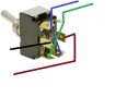
First of all the simple question, i need to wire up a simple passing loop. I know about having the power supplied from the toe end of the point, and isolating the two central frog tracks of the point, but i cant remember how to go about wiring the tracks into the dpdt switch.

Which kind of switch do i need, On/On or On/Off/On? and do i need one with 3 pins on the bottom or with the 6 pins?
Do these switches need to be permantly weatherproofed inside a tuppaware box or inside a building of some sort?


Secondly, to power our tracks, we use two of these, http://www.maplin.co.uk/p/100w-slim-bench-power-supply-n93cx , one for each loop. These have always perfectly suited our needs, but the only trouble is that to change direction of travel, you have to switch over the 2 wires in the front of the power supply. Is there a way in which a similar dpdt switch could be wired in between the track and the transformer to allow polarity to be changed via a flick of the switch rather than swapping the wires over each time?

Would this switch need to be weather proofed at all times? (The power supplies come inside after each running session)
Would i need a special switch capable of handling the high amps or would a normal toggle switch be ok?

Any wiring diagrams for either problems would also be much appreciated!

Many thanks
Matt
 
For the loop you want a single pole double throw(contact) switch. You don't need a centre off unless you want to use this to isolate both tracks.
For the power supply, use a DPDT. power to the two centre terminals and connect the outer to the rails - but alternate way round for each pair of terminals..
 
As Alan says..
A single pole changeover switch (SPDT) will have three terminals..
The Double Pole, Double Throw (DPDT) switch will have six terminals..
All are available from Maplin.
 
That seems simpler than expected for the transformer switch..

I just found this wiring diagram i had last year for a siding,
2014-04-15 09.31.39.jpg

i presume it would just be the same for a passing loop. Would i need to do this at each end of the passing loop or just on one of the points? I presume i need to do it for both points and can wire them all into the one switch?

Do these need to be waterproofed then or could i just fix them straight onto the wooden control panel that is left outdoors?
Also how do you attach the wires to the point? Are there terminals to attach directly to underneath the point?
 
??? Hang on minute, this seems to be getting overly complex for what is a simple job.

Firstly, there is no need to have the feed wires at the toe end of the switch. LGB (and other) turnouts are what is call 'non isolating'... don't matter which way the switch is thrown, all tracks are live.

Question is, do you want to have the ability to 'power off' in the siding and/or main line?

Assuming the answer is yes, then, for a complete crossing loop you will need 4 insulations, and either 2 simple on/off switches, or 1 DPDT switch. You need to put the insulated joints on the rails just past the frogs, i.e. the 'inside' rails, leaving the 'outside rails' live contrary to the photo in the previous post. Run a wire from the live main line rail to the on/off switch then to the equivalent rail on the loop. Do the same from the live rail on the loop, back through a second switch to the isolated rail on the main line. This method will allow both lines to be alive, or dead, or choose what ever you like.

You can swap the two on/off switches for a DPDT centre off switch that will do all the above (except having both tracks live at the same time. For this explanation, assume the DPDT switch is 'vertical' i.e. 3 tabs on each side. Connect one live wire to the centre tab, and the other wire to, say, the bottom tab (on the same side). When the toggle switch is 'up', this will form a connection between these two wires, thus powering the track. On the other side, connect to the top tab, instead of the bottom. When the toggle is down, this side will be connected (and the other side disconnected). With the toggle at centre, all will be off.

I have just wired my Taita Gorge Railway using the simple on/off system described above. ;)
 
;) Now, for part two, reversing. I assume your control system does not have a reversing switch for power applied to the track (rather odd situation, most power supplies come with a reversing switch).

Back to the DPDT switch. To use one of these requires some dexterity with a soldering iron, as you will be having multiple soldered joints on the same tab. Simply solder the two power feed wires to the bottom of the three tabs, one each side. Next, the tricky bit, solder a short wire from the bottom left tab, to the top right tab. And do the same from right bottom to top left. From the centre tabs, solder wires that will run to the tracks.

When the toggle switch is 'up', it will connect the bottom tabs (which have power feeding into them) with the centre tabs, and onto the track. Now, because we have 'crossed wires' connecting the bottom and top tabs, when we put the toggle down, it will connect the top and centre tabs, sending power in the opposite direction to the track.

This is an extremely useful switch when you want to wire up a return loop. I put one in my return loop on the Taita Gorge Railway just the other day.

http://www.gscalecentral.net/g-scale-pictures/taita-gorge-railway
 
Stoopid work internet is blocking the page, but I think on this page there is a simple drawing of how to wire a DPDT switch to reverse DC power. I have a little box with such a switch plugged into my Maplin power supply on my workbench. Saves having to swap the banana plugs!

http://www.nmra.org/beginner/wiring.html
 
I have the same set up as suggested by Gavin controlling the polarity my reversing triangle. A bit of a mindbender without a diagram but pretty logical once you see how. With regards to weatherproofing - Yes, very much so. the Maplin switches have steel components that will rot to red dust within a couple of wet seasons if not protected or kept from immersion. Don't ask me how I know.

Interesting about which side the insulators go on the passing loop, thanks for that Gavin. That explains one or two things.
Max.
 
Thanks everyone, i had a pretty good idea of what i had to do but i always like to just confirm it before messing around the electronics!

will most likely get the wiring done this weekend. Just had a quick look on Maplins website and the one thing that always confuses me is that tthey do 6 pin dpdt switches in On/On, and On/Off/On.
I know i just need the On/On switch for the passing loop, and i presume the same for the transformer switching?

matt
 
matthew said:
Just had a quick look on Maplins website and the one thing that always confuses me is that tthey do 6 pin dpdt switches in On/On, and On/Off/On.
I know i just need the On/On switch for the passing loop, and i presume the same for the transformer switching?

matt

Matt, On/On is fine, actually either type of switch will work with the On/Off/On giving you the option of switching off completely in the centre position. The ones to avoid are those with an option in brackets such as (On)Off(On) or (On)On. With these to you have to hold them in place for the bracketed function as they are spring loaded to return the unbracketed position.
 
matthew said:
Thanks everyone, i had a pretty good idea of what i had to do but i always like to just confirm it before messing around the electronics!

will most likely get the wiring done this weekend. Just had a quick look on Maplins website and the one thing that always confuses me is that tthey do 6 pin dpdt switches in On/On, and On/Off/On.
I know i just need the On/On switch for the passing loop, and i presume the same for the transformer switching?

matt

I take it from this comment, you are only interested in turning the siding on or off, leaving the main line live. If that is the case, you only need to insulate the same rail in the siding, at each end, and run a wire, through a simple 2 tab on/off switch fro the equivalent live rail, to the isolated rail in the siding. Sooner or later, you will find that you will want the ability to turn off the main track separately, so the 2 switch, or DPDT system I described earlier is the way to go. How do I know you will want to be able to switch off the main? een there, done that.
 
No Gavin i would like it so that when one line of the passing loop is live the other is dead, and vice versa. I presume it's still fine to use an On/On DPDT switch. I dont need the ability to have both of the passing loop lines dead so no need for an On/Off/On.
 
[quote author=matthew link=topic=298714.msg313522#msg313522 date=1398494803]
No Gavin i would like it so that when one line of the passing loop is live the other is dead, and vice versa. I presume it`s still fine to use an On/On DPDT switch. I dont need the ability to have both of the passing loop lines dead so no need for an On/Off/On.
[/quote]

By the sounds of it you need only a SPDT switch to keep things simple. Isolator rail joiners in one rail at the ends of both loops and then wired through the SPDT switch to rest of the system.
circuit2.jpg

Rik
 
I managed to build the weatherproof control box the other day and built my switches into it. I had a go at the wiring for switching polarity of the transformers and got both of those working perfectly! Was still struggling to get the passing wiring around my head but i just went outside to have a play and got that working too, so thanks everyone for the help :)
 
ge_rik said:
By the sounds of it you need only a SPDT switch to keep things simple. Isolator rail joiners in one rail at the ends of both loops and then wired through the SPDT switch to rest of the system.
Rik
That would work. My personal preference though is to isolate the rails passing through the plastic frogs. I often do this by cutting the bonding strips under the points rather than insulated fishplates. Also this method provides uninterrupted power feed to the rest of the circuit as the two outermost rails are continuous.
 
ge_rik said:
By the sounds of it you need only a SPDT switch to keep things simple. Isolator rail joiners in one rail at the ends of both loops and then wired through the SPDT switch to rest of the system.
[attachimg=1]

Rik

No, that won't work, unless the track layout forms a complete circuit/oval. By breaking electrical continuity on the 'outside rails, you have lost power supply to the track past the breaks at the other end of the loop. As Neil has said, reinforcing my suggestion, the outside rails should remain continuous. Trust me, been there, done that.
 
Gavin Sowry said:
... the outside rails should remain continuous.

i am not sure, if i understnd this.
do you mean the outside rail of the loop/circle, or do you mean the outside rails of a turnout?

because in the latter case you would get unnecessary complications. the right and left leg of the turnout and its siding would have their interrupted rails on different sides/cables.
on my layouts i always tried to have one rail continous and uninterrupted through the whole layout.
(saving many meters of cable by using it as common for different speedcontrollers, signals, modellhouse lights and whatever else i need)
 
It's a trade-off between reduced wiring where a common rail is used, against (for example) desire to maintain the outmost rails of a passing loop as part of the continuous electrical circuit of the main line. Must admit I always fit the insulated joiners on the two frog rails (eg. the inside rails of a passing loop) the same as Neil and Gavin, but this is as much to do with my experience with live frog pointwork in the smaller scales as it is to maintain the continuous circuit path (I've converted some of my LGB points to true live frog and will probably do more as time allows).
 
Back
Top Bottom