timing signals query?

HobbitFertang

Registered
Country flag
Hi Folks, Is there a circuit board available for timing/switching 12V that doesn't involve programming. I'm thinking of switching green to red signal using a reed switch but with delay? or something similar?? This would be solar powered.
 
Another one from Amazon.... has a variable delay adjustable up to 60 seconds, which may be more useful for railway signalling purposes.. About AUD $18 for a pair in Australia, so probably about 9 quid in the UK.

IMG_6758.jpeg
 
Hi Folks, Is there a circuit board available for timing/switching 12V that doesn't involve programming.

I asked myself this same question some years ago.

As a convicted train watcher I wanted working signals on my line. I didn't want just one signal but a number of signals dotted around at various junctions and key positions that were just for visual reasons for my amusement. I had 13 working signals at one stage.

I decided to design my own signal controllers all based on the 555 timer. I must point out that I am no electronics expert but the 555 circuit is well explained on many websites. There may be a better way to control the signals but I can understand the 555 circuit

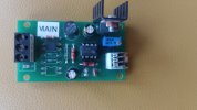
I had a small batch of boards made in China and assembled the components myself and ended up with these -

IMG_20260724_103505470.jpg
3 terminals on the left for track power and trigger. 3 spring clamp terminals on the right for the signal. It works on DCC and DC 12 to 30 volts.

The switched output is 12 volts. Depending on the components, the timed value is adjustable up to 60 seconds, 10 seconds will be too short especially with a slow running train.

I have a few of these going spare at the moment if you, or anyone are interested.

Some boards were assembled as a bi-stable circuit. Then you have a reed switch to switch on the signal and another reed switch further down the line to switch off the signal. This is how some of my signals are configured and I will have to use more of this version after adding an extra track at the main station. Using this method adds extra wiring but gives a more accurate operation that is not dependent on loco speed. In fact the loco can stop between the reed switches and the signals will not change until the loco is moving and passes the second reed switch.
Rather than convert my spare timer boards I will purchase some more new boards and build them in bi-stable configuration. If you are interested, please let me know.

I considered using reed switches but rejected them partly because of reliability issues and partly because all trains would require a magnet fitted to them. Visiting trains would not operate the signal.
My solution was to insert a very short section of dead rail into the track and wire that to the trigger on the circuit board. When a loco passes over the dead piece of track, it applies voltage to the dead section to trigger the signal. The loco is the switch.
Those with battery power, it is not as straightforward but with a short length of powered track that includes a trigger section and a loco that conducts power on 1 side it could work.

Alan

 
I asked myself this same question some years ago.

As a convicted train watcher I wanted working signals on my line. I didn't want just one signal but a number of signals dotted around at various junctions and key positions that were just for visual reasons for my amusement. I had 13 working signals at one stage.

I decided to design my own signal controllers all based on the 555 timer. I must point out that I am no electronics expert but the 555 circuit is well explained on many websites. There may be a better way to control the signals but I can understand the 555 circuit

I had a small batch of boards made in China and assembled the components myself and ended up with these -

View attachment 359180
3 terminals on the left for track power and trigger. 3 spring clamp terminals on the right for the signal. It works on DCC and DC 12 to 30 volts.

The switched output is 12 volts. Depending on the components, the timed value is adjustable up to 60 seconds, 10 seconds will be too short especially with a slow running train.

I have a few of these going spare at the moment if you, or anyone are interested.

Some boards were assembled as a bi-stable circuit. Then you have a reed switch to switch on the signal and another reed switch further down the line to switch off the signal. This is how some of my signals are configured and I will have to use more of this version after adding an extra track at the main station. Using this method adds extra wiring but gives a more accurate operation that is not dependent on loco speed. In fact the loco can stop between the reed switches and the signals will not change until the loco is moving and passes the second reed switch.
Rather than convert my spare timer boards I will purchase some more new boards and build them in bi-stable configuration. If you are interested, please let me know.

I considered using reed switches but rejected them partly because of reliability issues and partly because all trains would require a magnet fitted to them. Visiting trains would not operate the signal.
My solution was to insert a very short section of dead rail into the track and wire that to the trigger on the circuit board. When a loco passes over the dead piece of track, it applies voltage to the dead section to trigger the signal. The loco is the switch.
Those with battery power, it is not as straightforward but with a short length of powered track that includes a trigger section and a loco that conducts power on 1 side it could work.

Alan
Things move on but I was asked many years ago now to do a Tarining Model Railway for a Train Ooerating Company, the build of the railway was easy peasy after my redesign from just a circle, but the 4 Aspect thing that they needed was beyond my ken. Sadly the Model Railway Supplier at the time I contacted (the only one offering it at the time) was so greedy at supplying that we gave up the job.
 
Back
Top Bottom