Progress on The Orchard Line - posts in. Next up, cable trays!

DGE-Railroad

The Orchard Line
26 Jan 2020
607
89
52
United Kingdom
Best answers
0
Country flag
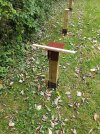
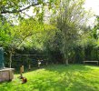
Thanks to a bit of sun and a helpful 3yo, The Orchard Line as it is now known is beginning to take shape.

The posts are pretty much in. It's amazing to see how much undulation there is in what ostensibly feels a 'flat' piece of land!

I'm just waiting on the arrival of a pipe location tool, to figure out where exactly the subterranean heating oil pipe goes. I really don't want to put a spike through it!

Next up, a pile of 300mm Hot-Dip-Galvanised cable trays so that work on the trackbed can start. I'm trying to figure out the best way to mount these to the posts - a stringer plate I guess, on top of the post and running in the direction of the track to add some rigidity to the span, but should I have some lateral support across the width of the cable tray on the of the post too? Any suggestions are most welcome.
20200906_150740.jpg
 

PhilP

G Scale, 7/8th's, Electronics
5 Jun 2013
33,561
3,521
Nottingham
Best answers
0
Country flag
Just be aware a lot of heating-oil (and tanked gas) pipes are plastics, these days.. :(
 
  • Like
Reactions: 1 user

DGE-Railroad

The Orchard Line
26 Jan 2020
607
89
52
United Kingdom
Best answers
0
Country flag
Thanks Phil. Yes that was a concern. It appears to be copper sheathed in plastic where it enters the ground but I have a feeling the copper probably gives way to plastic for the main run. I hope not but I'll stick a Genny on the pipe and sweep the area with a CAT to see if there are any emissions from it.

I don't really feel like excavating the pipe to follow it, so if it is undetectable my plan of action at the moment is to use some Wreckin Concrete large deck blocks for the 6 or so posts that would pose a risk :(
 

Rhinochugger

Retired Oik
27 Oct 2009
36,710
4,240
North West Norfolk
Best answers
0
Country flag
Thanks Phil. Yes that was a concern. It appears to be copper sheathed in plastic where it enters the ground but I have a feeling the copper probably gives way to plastic for the main run. I hope not but I'll stick a Genny on the pipe and sweep the area with a CAT to see if there are any emissions from it.

I don't really feel like excavating the pipe to follow it, so if it is undetectable my plan of action at the moment is to use some Wreckin Concrete large deck blocks for the 6 or so posts that would pose a risk :(

I think you'll find it is plastic-sheathed copper, and pretty delicate ......... and usually not protected by anything else

The guys who lay it usually come from Eidelberg :nod::nod:
 
  • Haha
Reactions: 1 user

PhilP

G Scale, 7/8th's, Electronics
5 Jun 2013
33,561
3,521
Nottingham
Best answers
0
Country flag
A crop of an advert...

Rhino Piling.jpg
I could do with a 'corkscrew' like this.. - Fence-post holes.. :):nod:
(notice the company name! :rofl::rofl::rofl: )
PhilP.
 
  • Haha
Reactions: 1 user

Paul M

Registered
25 Oct 2016
11,875
1,696
60
Royston
Best answers
0
Country flag
but should I have some lateral support across the width of the cable tray on the of the post too? Any suggestions are most welcome.
Try "Unistrut". Probably quite expensive but will match your cable tray
 

DGE-Railroad

The Orchard Line
26 Jan 2020
607
89
52
United Kingdom
Best answers
0
Country flag
Cheers Paul. To provide mounting points for the ends of the tray width?

I stumbled across a useful article on WesternThunder Here which nicely outlines someone else's approach and also addresses the issue of ballasting - something which I think would make a big difference aesthetically but which I was concerned would add a substantial amount of weight.
The site post would imply that if I want to ballast, angle iron or some other support will be necessary. That could prove a useful addition though as a C-channel or similar could also provide protection for the pneumatic pipework for the points. It's always. I've to have a single solution addressing multiple issues!

My thought had been a fine plastic mesh at the bottom of the tray to prevent ballast dropping through the tray holes while allowing drainage, then a fine layer of light 'ballast' over the top.
 

PhilP

G Scale, 7/8th's, Electronics
5 Jun 2013
33,561
3,521
Nottingham
Best answers
0
Country flag
My thought had been a fine plastic mesh at the bottom of the tray to prevent ballast dropping through the tray holes while allowing drainage, then a fine layer of light 'ballast' over the top.

I don't think you will find a 'plastics' mesh that is UV-stable enough for this?

I would suggest a 'geo-textile' membrane material. - Even weed control membrane, perhaps?

PhilP.
 
  • Like
Reactions: 1 user

GAP

G Scale Trains, HO Trains, 1:1 Sugar Cane trains
14 Jun 2011
4,057
940
Bundaberg Queensland, Australia
Country
Australia
ringbalin-light-railway.blogspot.com
Best answers
0
Country flag
I don't think you will find a 'plastics' mesh that is UV-stable enough for this?

I would suggest a 'geo-textile' membrane material. - Even weed control membrane, perhaps?

PhilP.

I would like to add shade cloth to the list of suggestions, UV stable and will help with the draining of water, as it will be under ballast the amount of UV that will get through will be small if any.
 
  • Like
Reactions: 1 users

GAP

G Scale Trains, HO Trains, 1:1 Sugar Cane trains
14 Jun 2011
4,057
940
Bundaberg Queensland, Australia
Country
Australia
ringbalin-light-railway.blogspot.com
Best answers
0
Country flag
Thanks to a bit of sun and a helpful 3yo, The Orchard Line as it is now known is beginning to take shape.

The posts are pretty much in. It's amazing to see how much undulation there is in what ostensibly feels a 'flat' piece of land!

I'm just waiting on the arrival of a pipe location tool, to figure out where exactly the subterranean heating oil pipe goes. I really don't want to put a spike through it!

Next up, a pile of 300mm Hot-Dip-Galvanised cable trays so that work on the trackbed can start. I'm trying to figure out the best way to mount these to the posts - a stringer plate I guess, on top of the post and running in the direction of the track to add some rigidity to the span, but should I have some lateral support across the width of the cable tray on the of the post too? Any suggestions are most welcome.

View attachment 272659
A cross piece with bracing (made from metal strapping? Bracing & Strapping available from Bunnings Warehouse) at each of the posts would be a good idea (that way you would not be drilling/screwing into the end grain of the post), if the distance between post is greater than about 1.2-1.5M then a support running lengthwise would be a good idea either down the centre of on each side. Most cable trays have a small "c" fold along the edge that can be used for wiring.
I investigated using cable tray for my new layout but ended up using hardwood because I had a ready supply for free.
I was going to use joist hangers to mount the timbers.

Note; Bunnings is an Australian large hardware warehouse chain store do not know of a UK equivalent.
 
  • Like
Reactions: 1 user

The Shed

Citizen of the Republic of the North East.
8 Mar 2020
1,070
238
Darlington, County Durham.
Country
England
Best answers
0
 
  • Like
Reactions: 1 user

DGE-Railroad

The Orchard Line
26 Jan 2020
607
89
52
United Kingdom
Best answers
0
Country flag
What a great community! Thanks for all of the input. UV stability is something to consider Phil but as GAP reasons, I'd wondered if being underneath the ballast would mitigate much UV risk in the first place. Shade cloth may be the way to go but I think I have some weed control membrane sitting unused, so could experiment with both.

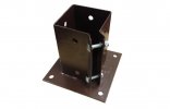
Thanks to GAP and The Shed for joining forces with the UK-accessible hanger solution :) That could certainly address the end-grain mounting issue. The hanger idea led me down a rabbit hole of Google images and I also found this which if inverted, might do nicely too.
bolt-down-plate.jpg

My original plan had been to mount the cable trays flat-side down, effecting making a 'U' to contain a thin layer of ballast and the track. I reasoned having vertical sides would add a handy safety-net for any derailments and was going for 300mm tray widths to accomodate twin tracks and a small amount either side.

Richard's approach on the WesternThunder posts is to use a narrower tray, mounted the other way up - forming an 'n' shape on top of which he's mounting 12mm hardiebacker boards - those impervious cement boards used in shower tiling and the like.

I'm struggling to decide which approach would work best?
- The U shape adds safety and allows drainage, but is restrictive in terms of width; adding spurs and accomodating changes is going to be harder.
- The n shape and deck adds makes for a free track area but adds weight and cost, particularly if I decide to a border to the board to act as a catchment.
 
Last edited:

GAP

G Scale Trains, HO Trains, 1:1 Sugar Cane trains
14 Jun 2011
4,057
940
Bundaberg Queensland, Australia
Country
Australia
ringbalin-light-railway.blogspot.com
Best answers
0
Country flag
What a great community! Thanks for all of the input. UV stability is something to consider Phil but as GAP reasons, I'd wondered if being underneath the ballast would mitigate much UV risk in the first place. Shade cloth may be the way to go but I think I have some weed control membrane sitting unused, so could experiment with both.

Thanks to GAP and The Shed for joining forces with the UK-accessible hanger solution :) That could certainly address the end-grain mounting issue. The hanger idea led me down a rabbit hole of Google images and I also found this which if inverted, might do nicely too.
View attachment 272700

My original plan had been to mount the cable trays flat-side down, effecting making a 'U' to contain a thin layer of ballast and the track. I reasoned having vertical sides would add a handy safety-net for any derailments and was going for 300mm tray widths to accomodate twin tracks and a small amount either side.

Richard's approach on the WesternThunder posts is to use a narrower tray, mounted the other way up - forming an 'n' shape on top of which he's mounting 12mm hardiebacker boards - those impervious cement boards used in shower tiling and the like.

I'm struggling to decide which approach would work best?
- The U shape adds safety and allows drainage, but is restrictive in terms of width; adding spurs and accomodating changes is going to be harder.
- The n shape and deck adds makes for a free track area but adds weight and cost, particularly if I decide to a border to the board to act as a catchment.


That device we call them post stirrups in Aust inverted would do the trick for me.
Then you could do away with the cable tray and use treated timber to make a ladder system which could be covered in the fibre cement (hardie backer).

I have used a ladder with fibre cement (see blog link "About the Railway" in my signature) but only because the timber was available and free (its my old verandah decking boards).

But after saying all that if you have to spend money personally I would go with the cable tray but as wide as I could get, 500mm maybe, and use the U shape config.

As for adding extra trackage just screw another piece of tray to the original and cut the side to allow the track to pass for support a piece of treated timber resting on a concrete plinth/ paver set 50mm into the ground and supported by one of the things shown in the picture would work for me.

Remember to seal all the cut and drilled ends if you do go down the cable tray route (Use a method the RAN call a "Wet Build" where each screw is dipped in silicone sealer or similar prior to screwing and a spray sealer on larger cuts.

Thinking even further out of the box maybe consider using a concrete plinth set 100-150mm into the ground and a stirrup to solve your drilling into the pipe problem.

Some more from Bunnings in Aust Stirrups available from Bunnings Warehouse

That should give you enough to think/worry about for now. :(:(:(
 
  • Like
Reactions: 1 user

DGE-Railroad

The Orchard Line
26 Jan 2020
607
89
52
United Kingdom
Best answers
0
Country flag
Thanks a million GAP, that's fantastic. Just the sort of food for thought that I need :)

I've just spend an enjoyable half hour scanning through the Ringbalin blog posts. Superb construction work. I love the trestles and lifting bridge too - both things I was looking to incorporate.
I'm doubly excited about incorpoating a trestle - not only do I love the look but it removes the need for any of this for a section or two :D

Great use of the old deck. I can see why it was a natural choice. As I need to but anyway, I priced up a wood ladder, a composite one, cable trays and cable ladders. The cable trays do seem the most cost effective.

You raise a very good point regarding sealing any cuts that are made. I can probably save money further by getting pre-cut galvanised trays, rather than hot dipped. pre-cut is cheaper as the blank roll is galvanised and then the form made/holes punched. This obviously leaves unprotected areas. Hot-dip is more expensive because the final form is galvanised. Given I'm likely to be cutting and protecting for bends/spurs and the like anyway, it might make sense to expect to paint all of the trays.

Great lateral thinking regarding the pipe avoidance too. I was getting too blinkered in my approach - a fresh pair of eyes on the problem and you've come up with a much easier solution. The concrete deck footings I'd considered only seem to be available from one place in the UK and it would mean a fair drive to pick up a small number. The plinth and stirrup/boot will achieve the same result using locally available bits, so I'll go that route.
 

GAP

G Scale Trains, HO Trains, 1:1 Sugar Cane trains
14 Jun 2011
4,057
940
Bundaberg Queensland, Australia
Country
Australia
ringbalin-light-railway.blogspot.com
Best answers
0
Country flag
Thanks a million GAP, that's fantastic. Just the sort of food for thought that I need :)

I've just spend an enjoyable half hour scanning through the Ringbalin blog posts. Superb construction work. I love the trestles and lifting bridge too - both things I was looking to incorporate.
I'm doubly excited about incorporating a trestle - not only do I love the look but it removes the need for any of this for a section or two :D

Great use of the old deck. I can see why it was a natural choice. As I need to but anyway, I priced up a wood ladder, a composite one, cable trays and cable ladders. The cable trays do seem the most cost effective.

You raise a very good point regarding sealing any cuts that are made. I can probably save money further by getting pre-cut galvanised trays, rather than hot dipped. pre-cut is cheaper as the blank roll is galvanised and then the form made/holes punched. This obviously leaves unprotected areas. Hot-dip is more expensive because the final form is galvanised. Given I'm likely to be cutting and protecting for bends/spurs and the like anyway, it might make sense to expect to paint all of the trays.

Great lateral thinking regarding the pipe avoidance too. I was getting too blinkered in my approach - a fresh pair of eyes on the problem and you've come up with a much easier solution. The concrete deck footings I'd considered only seem to be available from one place in the UK and it would mean a fair drive to pick up a small number. The plinth and stirrup/boot will achieve the same result using locally available bits, so I'll go that route.

More food for thought if you are adventurous use a trestle to go over the pipe area.

How deep do the heating pipes have to be in the ground?
In Aust most utilities phone water electricity have to be a minimum 600mm underground, sewerage even deeper.
Just thinking because all my posts holes are only 300mm deep then the posts are concreted in and they are very sturdy.

Looking forward to seeing this line evolve, have you considered writing a blog to record the progress over the years?
It is a bit daunting to start with, but quite easy once it is underway (google is your friend for how to's). I use Googles "Blogger" but there are others out there.
 
  • Like
Reactions: 1 user

PhilP

G Scale, 7/8th's, Electronics
5 Jun 2013
33,561
3,521
Nottingham
Best answers
0
Country flag
Not sure about any regulations.. But they are quite often 'half a spit' deep. - Just a slot 'cut' with a spade to half the depth of the blade. IF you are lucky..
 
  • Like
Reactions: 1 user

Rhinochugger

Retired Oik
27 Oct 2009
36,710
4,240
North West Norfolk
Best answers
0
Country flag
Not sure about any regulations.. But they are quite often 'half a spit' deep. - Just a slot 'cut' with a spade to half the depth of the blade. IF you are lucky..
It's probably covered in the boiler fitter's certification regs - not building regs.
 
  • Like
Reactions: 1 user

DGE-Railroad

The Orchard Line
26 Jan 2020
607
89
52
United Kingdom
Best answers
0
Country flag
So CAT-herine and Genny-fer were unable to detect the pipe. Predictable I suppose - it's probably plastic, or plastic sheathed. I followed it down into the ground for about a foot before giving up the excavation idea.

I'm just going to follow GAPs suggestion and dig out some small pad footings, line them with hardcore and make a little concrete pad for the post boots to bolt to.

The boots themselves inverted, look pretty good to make a snug and broad mounting point for the tops of the posts. That little strip of wood balanced on the top is 450mm wide, which is the cable tray width I'm now planning to go with

20200910_161038.jpg