BR95009
Registered
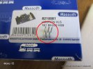
Installing a decoder Massoth eMOTION XLS (8210081) in the locomotive BR 99222 (LGB 26811).
The pics by numbers:
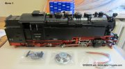
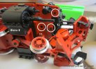
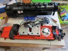
1) Everything is ready to install. Foam pad and a trapezoid to serve H0 locks are very useful.
[attach = 1]
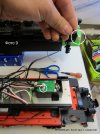
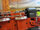
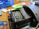
2) Remove the cover of the coal box that it would not break off when you turn the lock.
[attach = 2]
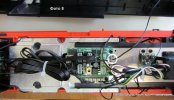
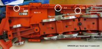
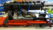
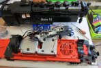
3) Bottom view.
[attach = 3]
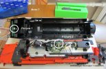
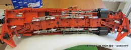
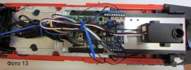
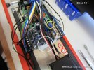
4-6) Unscrew the screws (in white circles, 1-2 - it`s up / down). 9-10-11 screws holding the front area with stairs, which unscrewing, get access to the last 12 screws.
[attach = 4]
[attach = 5]
[attach = 6]
7) Remove the top. Front and rear lights unfastened from slots 1 and 2.
[attach = 7]
8) Remember where the place of plug of front light.
[attach = 8]
9) Cable, which all strongly suggest soldering in smoke generator to synchronize the audio (and that comes with a decoder), have lovingly soldered by engineers of LGB.
[attach = 9]
The pics by numbers:
1) Everything is ready to install. Foam pad and a trapezoid to serve H0 locks are very useful.
[attach = 1]
2) Remove the cover of the coal box that it would not break off when you turn the lock.
[attach = 2]
3) Bottom view.
[attach = 3]
4-6) Unscrew the screws (in white circles, 1-2 - it`s up / down). 9-10-11 screws holding the front area with stairs, which unscrewing, get access to the last 12 screws.
[attach = 4]
[attach = 5]
[attach = 6]
7) Remove the top. Front and rear lights unfastened from slots 1 and 2.
[attach = 7]
8) Remember where the place of plug of front light.
[attach = 8]
9) Cable, which all strongly suggest soldering in smoke generator to synchronize the audio (and that comes with a decoder), have lovingly soldered by engineers of LGB.
[attach = 9]