You are using an out of date browser. It may not display this or other websites correctly.
You should upgrade or use an alternative browser.
You should upgrade or use an alternative browser.
Help With LGB 65000 Sound Unit Please
- Thread starter Madman
- Start date
idlemarvel
Neither idle nor a marvel
There was a long thread about this a few years back
How to increase chuff rate on LGB 65000 sound module - G Scale Central
But I don't think there was a simple answer as it got a bit of thread drift about smoke units etc, but worth a read.
Are you able to change CVs on a decoder? That seems to be essential to move forwards.
The manual says there is a decoder in the sound unit. Do you have the wheel magnet sensor installed? If so there is a way to increase the number of chuffs per rev from 2 to 4, and to adjust the wheel diameter which would in turn change the rate of chuffs. That should be in the wheel sensor manual which I can't track down, but it is set in CV64 somehow, not described in the 65000 manuals.
If you don't have wheel sensor then it seems to me (I don't have one of these so I am deducing from the manual) that you need to adjust the speed setting CVs CV2 and CV5 so that the speed of the chuffs matches the speed of the wheels.
Does the loco you have fitted this to have a motor decoder or is it analog? Here's where it gets even trickier. One version of the manual for LGB 65000 gives different CVs to change the speed if you are analog (CV 58 and CV59) or the "standard" ones if you are digital (CV2 and CV5).
So if your loco is analog try changing CV2/5or CV58/59 to change the speed at which chuffs start and rate at max speed
If you loco is digital, isolate the motor decoder then change CV2/5 as above.
Bit rambling but hope this helps. I see someone else has posted while I write this, I hope it says the same sort of thing or has a better answer!
Madman
Registered
Hmm, this is getting a bit over my head. The unit is new. It has the external volume control, not like the one pictured in the instructions shown in the link that Dave posted. I don't know if that matters.
Since I don't have the equipment specified in the instruction manual, https://www.onlytrains.com/pdf/I65000.pdf, I don't see how I can make the changes.
Phil mentioned using magnets and reed switches on the wheels to activate the chuffs. Where would the reed switch be plugged into on the 65000 ?
Just found the answer. It's pictured on the PDF. This may be the best solution for me, since programming seems to be out of the question.
Madman
Registered
So I did some investigation. The open port in the photo looks like the obvious place to plug a reed switch into. Unfortunately, I don't have a plug that will fit into the port. Also, there are three prongs in the port. A reed switch only requires two wires. I'm more confused. Is there an LGB part number for the proper cable to use here ?
So I did some investigation. The open port in the photo looks like the obvious place to plug a reed switch into. Unfortunately, I don't have a plug that will fit into the port. Also, there are three prongs in the port. A reed switch only requires two wires. I'm more confused. Is there an LGB part number for the proper cable to use here ?
Dan,
For preference, that port is designed for a Hall-Effect sensor, which uses three connections.. These are available from Marklin/LGB or Massoth, and just plug in to the sound module.
The other end of the cable is a small circuit board, which would slot into an LGB motor-block. there is also a ring magnet to fit on the axle. - You have to remove a wheel for this.
The other port (again, three wires) is for reed switches to be triggered by track magnets. - Usually used for whistle/horn and bell.
I am trying to find a full service manual for the 6500n series of sound cards, to see if the unit will accept a signal from a reed / magnets, but no luck so far.
PhilP.
Madman
Registered
Dan,
For preference, that port is designed for a Hall-Effect sensor, which uses three connections.. These are available from Marklin/LGB or Massoth, and just plug in to the sound module.
The other end of the cable is a small circuit board, which would slot into an LGB motor-block. there is also a ring magnet to fit on the axle. - You have to remove a wheel for this.
The other port (again, three wires) is for reed switches to be triggered by track magnets. - Usually used for whistle/horn and bell.
I am trying to find a full service manual for the 6500n series of sound cards, to see if the unit will accept a signal from a reed / magnets, but no luck so far.
PhilP.
So your talking about fitting the "small circuit board" to a locomotive axle. Can I fit it to a trailing car axle instead ? Would you happen to have a number or link the the Hall Effect Sensor ? Again, would it work on a trailing car ?
Thanks, Phil, for your help thus far.
So your talking about fitting the "small circuit board" to a locomotive axle. Can I fit it to a trailing car axle instead ? Would you happen to have a number or link the the Hall Effect Sensor ? Again, would it work on a trailing car ?
That is correct..
Shows the Massoth unit(s)
Instructions:
Who have stock, your side of the pond..
PhilP.
Madman
Registered
Massoth has been kind enough to correspond with me on the LGB sound module. But I am looking at what Phil sent as the most likely solution for a computer challenged mind. The Hall Sensor. I don't see why this couldn't be mounted to the trailing car's axle. The only question I have would be the male plug on the end of the cable. Will it fit into the female socket on the LGB 65000 ? The one with the little wheel symbol.


Madman
Registered
The socket with the bell and whistle pix above are for reeds for bell and whistle. Middle pin is common to both reeds. Wagon wheel socket is chuff which originally was only to be used for steam engines.
Thanks Dan. I cannot seem to get a straight answer from Massoth to my question. I wanted to know is the sensor could be mounted to an axle on my trailing battery car. That's where my 65000 os housed.
From what I see there is a magnet that normally would mount on a locomotive drive wheel axle and the hall effect sensor mounts in such a position that the magnet does what it is supposed to do to the sensor. I figure what's the difference between a locomotive axle and an axle on a freight car ? The freight car axle would simply have to be beefed up, the way I see it.
What do you think ?
idlemarvel
Neither idle nor a marvel
I can't see why not, the only difference might be wheel diameter, which would mean the chuffs might be a bit faster if the freight car wheel was smaller than the loco wheel.
Dan,
I think Masoth are 'covering their ass'.. - Don't want any comeback if you break things / it does not work for you..
I am sure a man of your calibre, can mount a ring-magnet on an axle? - It might need a bit of fiddling to get the separation correct, between sensor and magnet/axle, but no-worse than cabinet door-hinges!
Madman
Registered
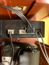
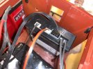
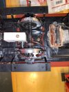
Hm, I am at a standstill. The eMotion Hall Effect sensor arrived yesterday and I installed it in my battery trailing car, which also houses my G Scale Graphics Railboss Plus receiver and related parts that transfer power via cables to any one of my locomotives.
Once the installation was complete, I fired it up. Nothing happened other than the original voltage activated sounds. I spun the wheel that has the magnet supplied with the Hall effect sensor and it had no effect on the chuff rate.
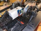
I have attached some photos of the installation. The magnet was super-glued to an LGB axle. The hall effect sensor was placed in a position mimicking the placement on a locomotive axle. The cable was plugged into the appropriate socket on the 65000 sound unit.
What am I missing ?


It might be a little 'off' and perhaps too far away? - Black-bit in-line with magnet, and perhaps a little less gap?
We any also be a a point where you need a local, tame DCC user?? - I fear a CV will need changing.. Just need to find the 'damn-paperwork'..
..
..
T'would appear to be CV 64, but the paperwork, so far, is less than helpful..
We any also be a a point where you need a local, tame DCC user?? - I fear a CV will need changing.. Just need to find the 'damn-paperwork'..
..
..
T'would appear to be CV 64, but the paperwork, so far, is less than helpful..
Madman
Registered
It might be a little 'off' and perhaps too far away? - Black-bit in-line with magnet, and perhaps a little less gap?
We any also be a a point where you need a local, tame DCC user?? - I fear a CV will need changing.. Just need to find the 'damn-paperwork'..
..
..
T'would appear to be CV 64, but the paperwork, so far, is less than helpful..
If it comes to programming, I am up that preverbal creek and I certainly do not have a paddle.....
As I am unable to find anything other than the 'default' value, and range, for CV 64... I have asked Massoth if they made these units, and can enlighten me:
CV 64 range 9-255 default 82
Can be used to set chuff if wheel diameter of axle with sensor is different to loco, and for use with magnets / sensor..
That is about all I have found, so-far.

Shirley, 'we' can find someone (more!) local to you, than me (!!!) who, push-comes-to-shove, you can send the unit to, to have the CV set..

CV 64 range 9-255 default 82
Can be used to set chuff if wheel diameter of axle with sensor is different to loco, and for use with magnets / sensor..
That is about all I have found, so-far.
Shirley, 'we' can find someone (more!) local to you, than me (!!!) who, push-comes-to-shove, you can send the unit to, to have the CV set..
I seem to remember that it needed a couple of trips around the line before the sound unit realised there was a sensor.
Without a battery, they need about 5-6V to wake-up.. A pity, as Buhler motors move from 2-3V!
Madman
Registered
I seem to remember that it needed a couple of trips around the line before the sound unit realised there was a sensor.
Tried that. I think the sound unit must be brain dead.....
