Harz Type Battery Railcar with some Playmobil abuse to create a New Battery Operated almost like.

dunnyrail

DOGS, Garden Railways, Steam Trains, Jive Dancing,
Staff member
GSC Moderator
25 Oct 2009
26,067
4,976
75
St.Neots Cambridgeshire UK
Best answers
0
Country flag
The Harz Lines have had a few Railcars in their time. The first being the little 4 Wheeler T1 built by Dassau as long ago as 1933 and the subject of a Trainline 45 Model that some day I may get hold of. Sundry Bogie Railcars have also been dabbled with over the years and these 1950’s built machines have a few still in service today as depicted by these examples below.
815B049F-63AA-4934-BDC3-484E672A278D.jpeg
2215E837-AF5A-4046-9452-48CB7BD1D78F.jpeg
But as the pic below shows the Harz was not beyond further dabbling and in 1996 the machine seen poking its head into the frame appeared.
D641EED8-17B8-4452-977D-E8B4B7837319.jpeg
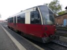
Followed in 1999 by 4 other machines built at Halberstadt to a slightly different specification as seen below.
3FCBF295-BFEB-489F-9E07-AC7F0FA08156.jpeg
A71AB9E7-65C4-4D33-81B9-C317A0D51668.jpeg
However my car of choice in this project is the Wittenberge 1996 machine as this has a closer fit to the PM Cab Profile, an important consideration.
2068F53A-207F-480C-87D4-8B27EEBDD5EE.jpeg

E7514ACE-DE55-47B1-A393-BDE23F9468D1.jpeg

CDD18085-22AD-4528-A7AB-01403A5321CC.jpeg

A352C60C-44B7-4BF7-9CD3-4467E2FBD6F8.jpeg

Here are some pics of the PM rolling stock that will be sacrificed in this Bash, a Bash that will not I am sorry to say be an exact replica but a sort of look alike having I hope much of the feel of the real thing. As to wether I will adopt the dual colour scheme or cop out for the all Maroon that has been carried by this unit remains to be seen.
B4C6A3BF-7DDA-4D17-BA77-C4CFA708A744.jpeg
1C971EDD-F873-4107-910B-99A56ACAFCD5.jpeg

So hold your breath, say a little prayer for whatever daity it is that is in charge of protecting PM Rolling Stock and enjoy what will be a White Knuckle ride.


Attachments

  • 2716B5BB-4669-4A41-A424-262DD1C26F3A.jpeg
    2716B5BB-4669-4A41-A424-262DD1C26F3A.jpeg
    831.8 KB · Views: 0
Last edited:
  • Like
Reactions: 1 user

playmofire

Registered
23 Oct 2010
8,245
852
80
North Yorks
Best answers
0
Country flag
This looks very interesting, Jon. I've often thought that the Panorama coach itself has good potential for conversion to a simple railcar but using the 4010 as well looks better still.
 

idlemarvel

Neither idle nor a marvel
13 Jul 2015
3,136
801
Ascot
Country
Mars
Best answers
0
Country flag
Good piece of lateral thinking there Jon, cut a loco in half and stick a passenger car in the middle. Having seen your previous work I'm sure this will be good too.
 

Rhinochugger

Retired Oik
27 Oct 2009
36,541
4,234
North West Norfolk
Best answers
0
Country flag
Some of them are better looking than others - the railcars I mean :cool::cool:
 

dunnyrail

DOGS, Garden Railways, Steam Trains, Jive Dancing,
Staff member
GSC Moderator
25 Oct 2009
26,067
4,976
75
St.Neots Cambridgeshire UK
Best answers
0
Country flag
Yesterday I did make a start but never had time to post so here goes with yesterday’s thoughts and actions.

First up was to set things down and do a little measuring. All the bits on the workbench with the inevitable Schweers and Wall book of the Harz Drawing as a starting point. Plus my rough sketch of what could be possible. I have a need to keep this to the 60cm around max length. You can see that the bottom sketch blew this some, but the revision on top was near enough so time to get cutting.
0DDEB8B6-F06A-4326-8B72-15ECE431A563.jpeg
But first some destruction and as with all things PM this was not quite so easy. On the Loco however there are some screws to undo as shown in the pic below, my felt tip lines show where they are. The Bogies popped off with a little brutal shove from below with a good large screwdriver. All of the Lighting Electrics were also taken out at this stage for possible future use.
25B8EAC4-3581-4FFC-986A-BBF42AA77A32.jpeg
But before any cutting I marked up the Chassis and Body to set the parts as the Chassis is ended!
20BAC210-3AA8-43A8-BD55-9C76DFB80B93.jpeg
Time to start cutting so careful lines were added using a Pencil and trusty Metal Tool as shown later. Here can be seen the Body with the lines of cut marked up.
A4CCE388-4B16-409F-B6EF-981C8345C1BD.jpeg
Cutting was done with a trusty Razor Saw using the deepest blade possible and brand new one at that. Here you can see the result of around 30 minutes work and the Tools used.
23E4FCF8-683B-4CCB-B3F3-B98B7EE4B771.jpeg
The underneath of the Chassis will have some of the mouldings left over from the Bogie Holding Tabs, these and the buffer Heads have all been removed and sanded clean as were the cut area’s of the body etc.
165BE68E-8028-4524-A63C-0AB33E4EE294.jpeg
Next up the Coach demolition. The Bogies on these are a tougher nut to release due to the lack of access for the same big screwdriver. So a smaller one below and one to press one of the Tabs in below with a lot of grunt soon had the 4 Bogies removed. Then as per the Loco. Marking up and cutting. The Chassis part of the Coaches has some pretty deep plastic that the Razor cannot get through due to the depth, the trusty Mini Drill with a Round Saw Blade soon saw to this and the unwanted parts were removed. A sort of Corridor Connection is at each end and this pops out easily with the application of the screwdriver. Again the Buffer Casting and unwanted mouldings are removed from the end with the Razor Saw and some serious Sanding.
2FF5BEE3-5BD0-4E79-8511-CCA9D93881DD.jpeg1EED591C-9727-4ADC-8578-7BE5342A925D.jpeg
Next up underneath there is the Bogie Moulding and another to remove, another job for the MiniDrill and it’s saw blade.
7F902CBD-3449-4AFB-BE77-73DEF91C2A52.jpeg
Finally having done the devilish deeds of trashing 3 perfectly good PM Models it was then time for a rough to see how it would all hang together. Pretty well meets the needs though somewhat longer than wanted as the ruler will show. However it may still fit the run-around at Harzegerode, time will tell.

0181BABB-A119-457B-AF05-BAA5DB7176C9.jpeg
It could be shortened some by cutting one of the ends near where the joint is, but I think I will leave well enough alone at this stage. The liberties taken with the real thing can be appreciated at this time, but my little people in the Harz will be getting a quick load panoramic overhead view of the Mountains, just what the Doc ordered. Finally in case you were wondering the PM Motor Unit is not planned to be used, a couple of US Sourced Power Bogies as with my other Railcar are in stock for this job. A start has also been made on the u wanted Lettering and Colour Flashes, this was done with a FibreGlsss Pen plus some WetnDry very fine paper.
 
  • Like
Reactions: 1 users

casey jones snr

Registered
20 Apr 2010
11,888
7,462
73
Charnwood Forest Railway. Rothley. Leics.
Country
England
Best answers
0
Country flag
Yesterday I did make a start but never had time to post so here goes with yesterday’s thoughts and actions.

First up was to set things down and do a little measuring. All the bits on the workbench with the inevitable Schweers and Wall book of the Harz Drawing as a starting point. Plus my rough sketch of what could be possible. I have a need to keep this to the 60cm around max length. You can see that the bottom sketch blew this some, but the revision on top was near enough so time to get cutting.
View attachment 256712
But first some destruction and as with all things PM this was not quite so easy. On the Loco however there are some screws to undo as shown in the pic below, my felt tip lines show where they are. The Bogies popped off with a little brutal shove from below with a good large screwdriver. All of the Lighting Electrics were also taken out at this stage for possible future use.
View attachment 256713
But before any cutting I marked up the Chassis and Body to set the parts as the Chassis is ended!
View attachment 256714
Time to start cutting so careful lines were added using a Pencil and trusty Metal Tool as shown later. Here can be seen the Body with the lines of cut marked up.
View attachment 256715
Cutting was done with a trusty Razor Saw using the deepest blade possible and brand new one at that. Here you can see the result of around 30 minutes work and the Tools used.
View attachment 256716
The underneath of the Chassis will have some of the mouldings left over from the Bogie Holding Tabs, these and the buffer Heads have all been removed and sanded clean as were the cut area’s of the body etc.
View attachment 256717
Next up the Coach demolition. The Bogies on these are a tougher nut to release due to the lack of access for the same big screwdriver. So a smaller one below and one to press one of the Tabs in below with a lot of grunt soon had the 4 Bogies removed. Then as per the Loco. Marking up and cutting. The Chassis part of the Coaches has some pretty deep plastic that the Razor cannot get through due to the depth, the trusty Mini Drill with a Round Saw Blade soon saw to this and the unwanted parts were removed. A sort of Corridor Connection is at each end and this pops out easily with the application of the screwdriver. Again the Buffer Casting and unwanted mouldings are removed from the end with the Razor Saw and some serious Sanding.
View attachment 256718View attachment 256719
Next up underneath there is the Bogie Moulding and another to remove, another job for the MiniDrill and it’s saw blade.
View attachment 256720
Finally having done the devilish deeds of trashing 3 perfectly good PM Models it was then time for a rough to see how it would all hang together. Pretty well meets the needs though somewhat longer than wanted as the ruler will show. However it may still fit the run-around at Harzegerode, time will tell.

View attachment 256721
It could be shortened some by cutting one of the ends near where the joint is, but I think I will leave well enough alone at this stage. The liberties taken with the real thing can be appreciated at this time, but my little people in the Harz will be getting a quick load panoramic overhead view of the Mountains, just what the Doc ordered. Finally in case you were wondering the PM Motor Unit is not planned to be used, a couple of US Sourced Power Bogies as with my other Railcar are in stock for this job. A start has also been made on the u wanted Lettering and Colour Flashes, this was done with a FibreGlsss Pen plus some WetnDry very fine paper.
Another brilliant project Jon. I’m looking forward to the next instalment.
 

JimmyB

Now retired - trains and fishing
23 Feb 2018
6,890
910
69
Weston-super-Mare
www.tumble-down-falls.co.uk
Best answers
0
Country flag
Jon interesting to see how this progresses.
 

playmofire

Registered
23 Oct 2010
8,245
852
80
North Yorks
Best answers
0
Country flag
Great work; look forward to the next stage.
 

dunnyrail

DOGS, Garden Railways, Steam Trains, Jive Dancing,
Staff member
GSC Moderator
25 Oct 2009
26,067
4,976
75
St.Neots Cambridgeshire UK
Best answers
0
Country flag
Thanks for the comments and likes guys, great confidence boosting.

Yesterday I decided to get some work done on the Chassis, as ever this involved some satisfying Metal Bashing. In the Shed I had a nice long length of Ally Sheet just the Right Width for the job. I think this was an inheritance from the Ruschbahn as there was a plan for a few Railcars on that line. So I roughed things together and realised that I needed to cut the length down some as I intend to mount some of the Electrics down below under the Cabs as that appears to be the place to offer the most space. Thus the base was cut to 47 x 9.5 cm, this allowed an overhand of 3/4 inch from the Passenger Sections at each end. Holes were drilled 44mm back for the Power Bogies to fit. I also around this stage glued the Top part of the Cab to the Passenger section giving me two parts to keep thing started neat. Joints were strengthened with bits of scrap Plasticard. A little filling will be required to get things nice and neat at the Joints. This allowed a rough up to see how things look with the Bogie. The dratted Grey Parts of the Cabs would not hold fast so they were temporary held in place with Blue Tack for this pic.
0871DD95-9389-41E3-91A0-E921DA6F5209.jpeg
This is a pic of the Power Bogies before modification, these came I believe from GRS, well they have been around for some time now. I initially thought that they had been used on the other Railcar, but were lurking in a different Box.
AD76ED44-1B75-4697-B1B8-8FDB26DE932F.jpeg
I have used a few methods to mount these but the favourite is to use the screws that hold the Thrust Bearing in place, one just has to ensure that when the Mounting Plate is fitted one does not screw the screws too far in to make the Bearings too tight. The Mounting thickness and a couple of small BA Washers normally takes care of this. A quick Power Test proves the job. Some flat Strip 8mm x 1.5 serves as the Mounting and Pivot Piece, Brent up and drilled for each end and then drilled for a 8ba (I think) Screw to be Silver Soldered for the Pivot. After the Screw is in place some fine Rod is Soft Soldered to act as Wobbling Points, one sideways the other forwards. Final job on the Bogies was to remove the Pickup Sliders and put all the bits thus removed in a Marked Up Plastic Bag to be lost in a Box if ever they are needed! Pics shows mods carried out before I removed the Sliders.
E9482F75-8D0A-4C9F-BF8A-4330A6D382A2.jpeg
Now the Chassis Plate with the Bogies in place, note the short under hang of the Plate.
B7F5CC7B-A468-44AE-B74B-DE8FA66D45FD.jpeg
I will at some time add some Angle with Pop Rivets to ensure that the Chassis Plate does not flop about. But the final work yesterday was to remove the Seat Fittings, these being for PM Figures to be placed into are somewhat large and would restrict the seating that I intend to fit on new flooring. A job for Mr Mini Drill with his trusty Round Saw Blade.
A554FD10-11D9-42A0-A682-A44C7879DE2A.jpeg
 

PhilP

G Scale, 7/8th's, Electronics
5 Jun 2013
33,451
3,504
Nottingham
Best answers
0
Country flag
I know there is not going to be a great deal of weight, but the motor-blocks (USA Trains, as used on the NW2, and others) are designed to be supported by the extended axle-ends, in bearings.
Not sure how robust the plastics of the 'blocks is, but just watch out for wear from the axles.. :nerd:
 

dunnyrail

DOGS, Garden Railways, Steam Trains, Jive Dancing,
Staff member
GSC Moderator
25 Oct 2009
26,067
4,976
75
St.Neots Cambridgeshire UK
Best answers
0
Country flag
I know there is not going to be a great deal of weight, but the motor-blocks (USA Trains, as used on the NW2, and others) are designed to be supported by the extended axle-ends, in bearings.
Not sure how robust the plastics of the 'blocks is, but just watch out for wear from the axles.. :nerd:
Thanks for that, I have been running a GRS Diesel and the former Ruschbahn Railcar Built like this for many years now. My other recent completion of a Ruschbahn startup is similar. In truth my running is not like many others, I do not indulge in hours of running round in ever decreasing circles. Timetable Running generally is a fairly sedate affair in terms of Mileages achieved over a days 3-4 Hour session. Plus I do not expect feats of great strength up horribly steep inclines like some seam to expect. Thus for now I have few worries about Chassis longevity ...... for now!

So today has seen some more effort. It has been getting towards joining the 2 Coach Sections together time. But as the bits to be joined have no through way some had to be cut. This pic shows the first one to be done with the markings for the other. I have left a lip in the bottom to maintain structural integrity of the body. Punters will need to step up and over this. Cutting these was a little bit of a task, I started out by using the Mini Drill with the Circular Saw to define a cut through the plastic on each of the lines. This was done twice over as the first cut will tend to melt the Plastic somewhat with the Speed required. The finish cuts were done with the trusty Razor Saw cutting a little over the lines so that all the cuts would join thus allowing the surplus Plastic to drop out. A small clean up with an old Nail Sandpaper Thingy completed the clean up. You can also see some test fitting of where Circuit Boards may fit, more of this next.

E6E196EC-0C57-49C4-9D6C-762631A9E462.jpeg
I realised that the Fakes I was trying to fit were for Fosworks DCC Kit so I needed to make up some more for the parts to be used in this Railcar. 2 bits of 5mm Hips are cut to size and glued together as shown here for the varying Boards.

4A6E2128-CA4C-4466-B1A9-98011E7AC3D9.jpeg

In the next pic you can see potential Hiding places for the Cards. They will be in Equipment Boxes faked up with Plasticard, the Sound Card will be below a removable Floor. Seeing that the sundry Cards can be easily accommodated is rather satisfying and a help to the way the way that work will progress.

6E933084-5DFF-4916-89FB-53DA6761A344.jpeg

25D3A947-E5A0-404B-9FF3-615B41BB9581.jpeg
Next up was to join the two sections in a more permanent way. A couple of holes were drilled in the bottom to take 8ba Nuts and Bolts that would secure the base. The Top is not quite so simple as the ends taper going up somewhat. So with a little difficulty a hole was drilled at the top end with the bottom secure then a Bolt with 3 nuts and a washer to act as a spacing used then finally secured at the top end with a completing Nut. This now gave a secure and accurately flat base to work with.
EAD946D6-2386-4F63-9741-CA48CAD25CFF.jpeg

83B62ADD-E716-47EB-8891-861ABF4BF224.jpeg
Then it was time to Pop River the Ally Angle to the Bottom Plate as shown below. I am not too fond of Pop Riveting considering it to be a crude job. However where nothing can be seen it works just fine. There speaks the man that built a Viaduct using Ally and Pop Rivets! The Angle is tight up to the edges of the lower protruding part of the Railcar, I will thus be able to use this as support when new additions are made to the underneath.
D5D6DD9E-FB93-4E93-93BB-69D082D064EA.jpeg
It was time to put some of the other parts in place temporarily to give a fel of the completed job. As can be seen the central joint will require some serious filling, but this cannot be done till I have put some Plasticard inside the joins so that the filler can not ouse out of the inside of the Joints. In this I am a little bit stuck as I need to get some suitable Liquid Plastic Weld having exhausted supplies the other day. The lack of Model Railway Shops in my Area makes this a problem, I tried in an Arty Shop in Cambridge a week or so back so it looks like future progress may be hampered on this front till I next get to a Show. However I should be able to get a Bogie Side frame Master Made so that I can utilise my recently acquired Resin Moulding skills to further use.
F28CAB6E-58D9-4CF4-A188-F15BCC7370FF.jpeg
But undeterred I could check out if the Railcar will fit the Run Round Pinch Point at Harzegerode and yest it will fit just. This is required as the Railcars often are seen on my line heading and Shunting a Wagon or two. For comparison it sits next to an LGB Coach.
E64E5CE1-6833-4607-AD00-0B9B874D234F.jpeg
Final Pic today is Vertical Clearance Testing to access the Shed. Plenty of space but I think that overhang May be an issue in odd places, we shall see.
76810922-80EA-4136-983A-DF45A0F29E1C.jpeg
 
Last edited:

PhilP

G Scale, 7/8th's, Electronics
5 Jun 2013
33,451
3,504
Nottingham
Best answers
0
Country flag
Out of curiosity, has anybody converted, one of these Play Mobiles to 2.4 ghz, as its 27 Mhz does lose signal easy.

Do you mean the 'blue' motor-blocks? - Yes, dead easy..

I have one where I built the Tx10 into the original Playmobil handset, and put six AAA NiMH in the motor-block.
With hindsight, I think I could have got AA's in there? - or a 2S Li-ion?

It is in the boot of the car... Which is presently languishing at the garage.. :(

Oh, I only used the Playmobil handset (as a case) because I could. - A standard handset would be just as good.

PhilP.
 

JimmyB

Now retired - trains and fishing
23 Feb 2018
6,890
910
69
Weston-super-Mare
www.tumble-down-falls.co.uk
Best answers
0
Country flag
Do you mean the 'blue' motor-blocks? - Yes, dead easy..

I have one where I built the Tx10 into the original Playmobil handset, and put six AAA NiMH in the motor-block.
With hindsight, I think I could have got AA's in there? - or a 2S Li-ion?

It is in the boot of the car... Which is presently languishing at the garage.. :(

Oh, I only used the Playmobil handset (as a case) because I could. - A standard handset would be just as good.

PhilP.
Why 6 X AAA, as the original is 4 X AA, surely this increases the voltage by 50%.
 

PhilP

G Scale, 7/8th's, Electronics
5 Jun 2013
33,451
3,504
Nottingham
Best answers
0
Country flag
Why 6 X AAA, as the original is 4 X AA, surely this increases the voltage by 50%.

I'll answer this one, then shut-up in Jon's thread.. - I'll do a 'build-thread for it, once the car is back and bank-rolled!

4 x 1.5V 'proper' batteries = 6V.

6 x 1.2V NiMH = 7.2V. - You lose a little through the electronics, and I wanted to speed the LCE up a bit.

PhilP.
 

dunnyrail

DOGS, Garden Railways, Steam Trains, Jive Dancing,
Staff member
GSC Moderator
25 Oct 2009
26,067
4,976
75
St.Neots Cambridgeshire UK
Best answers
0
Country flag
Jon following with interest.

Out of curiosity, has anybody converted, one of these Play Mobiles to 2.4 ghz, as its 27 Mhz does lose signal easy.

I'll answer this one, then shut-up in Jon's thread.. - I'll do a 'build-thread for it, once the car is back and bank-rolled!

4 x 1.5V 'proper' batteries = 6V.

6 x 1.2V NiMH = 7.2V. - You lose a little through the electronics, and I wanted to speed the LCE up a bit.

PhilP.
No worries Phil, answers about the donor power unit are quite relevant. A similar setup to the Fosworks setup I am using in this would also work. Cobra Controllers run on 6-28 Volts so no worries about over powering.

Battery Power can be a little daunting till you get going, but the suppliers in my experience tend to be very willing to help out with queries and lack of understanding.
 

dunnyrail

DOGS, Garden Railways, Steam Trains, Jive Dancing,
Staff member
GSC Moderator
25 Oct 2009
26,067
4,976
75
St.Neots Cambridgeshire UK
Best answers
0
Country flag
Have spent a pleasant afternoon on the lathe drilling and tapping Bogie spacers to fit the side frames to. On my last Diesel Railcar that I looked underneath this morning I realised that I had used IP Engineering ones, but only had two more in stock so decided to make my own. In truth the IP ones would be a little large as the Metal to be used is roughly 5.5 mm x 1mm Strip that was in stock and almost depleted now. The 6mm Square Rod was cut into 4x 56mm Lengths and Drilled and Tapped 6BA, that is now depleted. Steel Nut Head Bolts have mostly been used to join things together but a few off cuts of Thread have been used with nuts as well to save cutting down longer Bolts. The drawing shows the bits that will be added for detail, I have gone off the idea of using Resin Casting for this and will be fabricating all the parts, utilising Silver Solder to attach most of them. The outside of the Axle Guards are going to use what appear to be Dust Caps in stock and the Wiggly Springs are going to use Brass Screw Fit Model Lights sans the Glass. The Center Spring will be made up from KS Tubing with sundry bits of Brass for the other odds and ends. Note that the overhang is different, the Hidden End is just that on the real thing so not point in having things longer than needed.

Below the parts joined up at close of work today.
AD2F3324-4B6D-41BD-ACBD-C8D4AF401A5B.jpeg
This is as good a close up as I can get if the Bogie, it appears that the real thing has some slight differences from the Drawing in the SnW Book. Not to worry my Bogies are a little longer, but this is not to be a slavish copy of the real thing, just a sort of like it. At least you can see how the front end of the Bogie is hidden.
EC19CA2F-92CF-4FD4-9A2B-84020BDB2C4B.png
 

Riograndad

Model Railroading, boats and oil painting,
6 Jul 2013
2,161
639
69
Northampton UK
Best answers
0
Country flag
Interesting and following this one,coming on well Jon;););)
 

dunnyrail

DOGS, Garden Railways, Steam Trains, Jive Dancing,
Staff member
GSC Moderator
25 Oct 2009
26,067
4,976
75
St.Neots Cambridgeshire UK
Best answers
0
Country flag
Having got the Bogie Frame done it was time yesterday to start detailing. Oblongs were cut and drilled for Axle Holes, this was carried out after they had all been shaped together whilst in the Vice. Clamping and drilling them all together ensures accuracy when fitting to the Frame. All of the joints in this pic have been Silver Soldered thus later on finer detail can be Soft Soldered with no worries about the main parts detaching. The Fabricated parts were thus Silver Soldered to the frame and the Holes opened a little to allow some flexibility for running. The Cross Brace and small Squares behind were then cut and also Silver Soldered in Place. Finally an Angle was fabricated to join the frame to the Power Bogie via the Thrust Bearing Screw. A similar setup will be fabricated at the other end but this will also incorporate an extension so that a Coupling Loop can be incorporated.

Remembering Phils advice Post 10, after looking at the other Railcar support has been provided.
7F99F412-EFFB-4780-B821-5F5812F83085.jpeg
The next Pic shows the workbench at the end of the day. All tidied up for the next session as I find that I get to a point whe I can find nothing to work with, that point had pretty well been reached last night.
BEB7C76E-0053-45F3-AFBE-FFC8A940ABFE.jpeg
 
  • Like
Reactions: 1 user

Paulus

Registered
13 Jan 2012
136
17
Best answers
0
Very interesting bash! Nice work on the bogies.
Looking forward to see the progress on it.