You are using an out of date browser. It may not display this or other websites correctly.
You should upgrade or use an alternative browser.
You should upgrade or use an alternative browser.
Getting a Playmobil shuttle unit to work
- Thread starter playmofire
- Start date
playmofire
Registered
There are no known extant instructions for this item but I've always followed what I do with LGB and other shuttle makes.I assume you have the instructions, so know how to wire it up to the track?
PhilP
playmofire
Registered
I was wondering in a similar frame of mind but more "does it have to be on a track set up with a split track with diodes towards each end to work". Also, I know of at least one shuttle where the loco has to be positioned so that it starts and runs right to left when setting things up and so I always try to follow that "rule" with any shuttle. And, of course, the loco has to be on a piece of track between the two diodes.Being a shuttle unit, I assume that the loco will pause at the end of the run before returning. The module isn't stuck in the pause mode, is it?
playmofire
Registered
Andrew, I have opened a conversation with you. To see it, click on the envelope top right by your username.
I’m not sure how I’d check this apart from looking at the relay? It’s all way over touching the contacts which I’d guess would be closed for a power feed forward/reverseBeing a shuttle unit, I assume that the loco will pause at the end of the run before returning. The module isn't stuck in the pause mode, is it?
No instructions, it was acquired in a job lot. Surely the circuit board just sits between the track and the controller, each having a red and blue wireThere are no known extant instructions for this item but I've always followed what I do with LGB and other shuttle makes.
-bbbb
Registered
I've attached some images to this message of a store shuttle unit which was previously on ebay and included instructions in German. Is this the system you have? The instructions say It has a couple types of magnets which I assume it uses somehow, and the train itself clearly appears to be specialized for using the rc motorblock with an electric track(but perhaps is also specialized for use with the magnets?). I don't know how it works, but maybe someone else can share some insight based on these images, that is if you confirm it's the same shuttle system.
Attachments


It is a different beast..
Designed for track-power.
Yes, you feed power in, and connect to the track the output, but you also need two gapped-rail sections, and a couple of diodes..
The shuttle detects when the loco passes one of the diodes, and stops the train.
After a delay, the train runs back the other way, until it passes the diode at the other end of the track.
PhilP
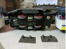
Excuse the nuts from the power to circuit board, they were just used to roughly nip the wires so I could get this photo. This is how I thought it would go together.
Power - Shuttle unit - track
Just to confirm the circuit works when the circuit board is removed from the equation
Power - Shuttle unit - track
Just to confirm the circuit works when the circuit board is removed from the equation
Attachments

Mine is just a standard track powered train, the shuttle is a playmobil one that came fitted to a buffer and the board is hidden in the buffer by sections of black card slotted insideI've attached some images to this message of a store shuttle unit which was previously on ebay and included instructions in German. Is this the system you have? The instructions say It has a couple types of magnets which I assume it uses somehow, and the train itself clearly appears to be specialized for using the rc motorblock with an electric track(but perhaps is also specialized for use with the magnets?). I don't know how it works, but maybe someone else can share some insight based on these images, that is if you confirm it's the same shuttle system.
I understand that I’d need diodes over gaps of track for the shuttle to send the train back and forth but surely with no diodes it should power the train anyway?It is a different beast..
Designed for track-power.
Yes, you feed power in, and connect to the track the output, but you also need two gapped-rail sections, and a couple of diodes..
The shuttle detects when the loco passes one of the diodes, and stops the train.
After a delay, the train runs back the other way, until it passes the diode at the other end of the track.
PhilP
Yes, but there could well be a delay, before the unit supplies power to the track. - The 'full' LGB units have a maximum delay of (up to) 8 minutes.I understand that I’d need diodes over gaps of track for the shuttle to send the train back and forth but surely with no diodes it should power the train anyway?
I thought even the simple offering, had a couple of pots to tweak?
PhilP
playmofire
Registered
I have found some photos of the version I had mounted on cardboard. They will follow in a few minutes.
playmofire
Registered
Here they are, excuse the dead spider, the shuttle came with it..JPG")
.JPG")
playmofire
Registered
The only problem now is deciding which pair of wires go where, track or transformer, and I have no photos to show this. What I would suggest is to set up alength of track with a split piece either end (with sufficient stopping room beyond with the diodes in (both on the same side of the track and "letting" current through in the appropriate direction) and then connect the shuttle to the track between the two split pieces, e.g. around the middle of the layout. If your controller has both an outlet for control and an outlet for auxiliary use, the wires to the track go from the control outlets to the track. If you are using a Playmobil controller, the outlets are the red and blue ones.
Here they are, excuse the dead spider, the shuttle came with it.View attachment 322157View attachment 322158
Attachments

So I took the board to work yesterday and had the electronics guy test it, when I had it attached to the controller and controller switched on he tested the other two wires with were reading a current of 12v.Yes, but there could well be a delay, before the unit supplies power to the track. - The 'full' LGB units have a maximum delay of (up to) 8 minutes.
I thought even the simple offering, had a couple of pots to tweak?
PhilP
So unsure why there should be a delay
Pedant-mode:So I took the board to work yesterday and had the electronics guy test it, when I had it attached to the controller and controller switched on he tested the other two wires with were reading a current of 12v.
So unsure why there should be a delay
A voltage of 12V..-Sorry,it just grates..
")
The unit could be faulty?
The problem with checking with a meter (without a load) is that a voltmeter is a very high resistance, so you need very little current to 'see' a voltage.
Despite it not having anything to set the delay times, I think it should be wired the same way as the filly-featured LGB unit.
Follow the breadcrumbs, to the LGB instructions:
Your controller is replacing the little unit they supply.
PhilP
Don’t worry I knew what I was saying as I was typing it. I was just trying to give all the info I had considering the 12v obviously not under load. Haha.Pedant-mode:
A voltage of 12V..-Sorry,it just grates..
The unit could be faulty?
The problem with checking with a meter (without a load) is that a voltmeter is a very high resistance, so you need very little current to 'see' a voltage.
Despite it not having anything to set the delay times, I think it should be wired the same way as the filly-featured LGB unit.
Follow the breadcrumbs, to the LGB instructions:
Your controller is replacing the little unit they supply.
PhilP
I will have a look at the instructions that you have sent, thankyou
Similar threads
- Replies
- 9
- Views
- 511
- Sale
- Replies
- 1
- Views
- 239