playmofire
Registered
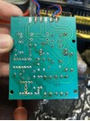
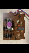
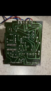
Hi Andrew (I guess it's you, Gordon here), James left the forum some time ago now, although it may still be that he keeps an eye on threads was involved with. Meanwhile, I've had a look at my Playmobil shuttle unit and the buffer with the elctrics in has a black plastic base over the innards which I am loath to try and remove. I had another version, where the innards were just covered with a piece of card, but that packed up years ago and eventually I ditched the innards but kept the buffer.Hello James, I’ve just acquired a playmobil shuttle unit. Unfortunately there seems to be a couple of components that have been removed from the circuit board, is there any chance you would be able to photograph both sides of your board please.
I’ve been scouring the internet for weeks trying to find info on these units.
Cheers
The Playmobil unit is very simple, for example, you cannot alter the time delay, and was, apparently a simplified version of an LGB one, which may explain why there appear to be parts missing on yours.
If you can post a photo in this thread of your version, I can then compare the electrics with the LGB version. If that doesn't help, then there are other Playmobil users on the forum who may know the answer.