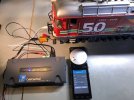
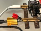
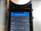
UPDATE ON THE ESU CABCONTROL DCC COMMAND STATION: I inserted a 25W 100Ohm resistor on one of the Program Output Terminal's wires to the Programming Track. Now the CABCONTROL can Read and Write CVs on the LGB locomotives (since 2014) with the Marklin MSD3 mfx/dcc/analog sound decoders installed........works like a charm!
Here's another data point about the ESU CABCONTROL DCC and ECOS Multi-Technology Command Stations and the Marklin CS3/+ Multi-technology Command Stations: Their Service Mode Programming Track output is continuously powered, not just when the Read or Write command is executed. On my CABCONTROL test the voltage was continuously 15.8 volts DCC except when I executed a Read or Write command, my DCC RRampMeter then read 13 - 11 - 13 then back to 15.8 volts; the output on the Main was 19.8 volts DCC. I could also activate the motor movement and F Key sounds on the Programming Track.
In fact, the ECOS User Guide states that the Programming Track can be used as a secondary output to a isolated block on the Main Track similar to a Booster. I'd be interested in understanding why ESU and Marklin designed their Service Mode output in this manner, perhaps it's required for their mfx, M4 and other non-DCC protocols. So obviously the DCC protocol for Service Mode Programming in these ESU and Marklin products are not compliant with the NMRA DCC Standard........interesting!


Last edited:

