CS3 Problems

phils2um

Phil S
11 Sep 2015
1,522
423
Ann Arbor, Michigan
Country
United-States
Best answers
0
Country flag
This is from the Massoth manuals Technical Data pages

8156001 4K module approx. 30mA
8156101 4K II module approx. 30mA
8156501 1K module approx. 30mA
8157001 Reverse-loop module approx. 50mA

LGB does not provide this info but their modules were made by Massoth and are basically identical except for housing color. I assume current needed to power the LGB devices is similar if not the same.

MD Electronics lists their SWD decoder (single channel servo decoder) and PWD (2 function lighting decoder) as having a current requirement of 5mA with no functions active.
 
Last edited:

duncan1_9_8_4

Jack of all trades on the Railway
25 Oct 2009
3,302
504
40
Pontefract, West Yorkshire
Best answers
0
Country flag
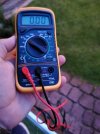
Just bought a amp meter. What should I be seeing on its display. I won't pretend to know. Its come with no instructions what so ever. IMG_20210820_204618.jpg
 

PhilP

G Scale, 7/8th's, Electronics
5 Jun 2013
33,561
3,521
Nottingham
Best answers
0
Country flag
Not a lot, probably..

You are measuring DC Amps, with your meter, but your CS3 is putting out an AC waveform.
 

duncan1_9_8_4

Jack of all trades on the Railway
25 Oct 2009
3,302
504
40
Pontefract, West Yorkshire
Best answers
0
Country flag
Not a lot, probably..

You are measuring DC Amps, with your meter, but your CS3 is putting out an AC waveform.
That means absolutely nothing haha. I'll just keep replacing the joints as it seems to have worked so far, and this contraption only cost a tenner.
 

jimmielx

45mm gauge track - approx 16mm scale (1:19)
24 Oct 2009
786
41
Hastings, UK
Country
United-Kingdom
Best answers
0
Country flag
I’d just keep replacing the joints…!

The meter will come in handy one day even if just for basic continuity checking (the red position near the bottom on the dial).
 
  • Like
Reactions: 1 user
8 Mar 2014
7,806
972
San Diego
Country
Armenia
www.elmassian.com
Best answers
0
Country flag
The page answering your questions was already provided as a link.

Set your meter to AC volts, put a load at the far end, etc.

Just replacing the joints is not on a good path to resolve the issue, you need a way to test under load.

You need to make a load, break the circles, and then put the load at the far end, then you can quickly find the problem.

Greg
 

dunnyrail

DOGS, Garden Railways, Steam Trains, Jive Dancing,
Staff member
GSC Moderator
25 Oct 2009
26,164
4,989
75
St.Neots Cambridgeshire UK
Best answers
0
Country flag
Just bought a amp meter. What should I be seeing on its display. I won't pretend to know. Its come with no instructions what so ever. View attachment 289072
My 2 pictures showed the position for continuity and voltage checks. As a rule the position you have it now will check DC voltage below 20v. So useful to tell you the status of say a battery voltage. If it has an on/off button do not forget to turn it off when you have finished using it otherwise you will run down the internal battery. How do I know this? Don't ask!
 

AlanL

Registered
1 Mar 2016
146
19
Northampton
Best answers
0
Country flag
Duncan, just want to give you some help with your multi-meter, I suspect you are struggling in the dark and apologies if I am stating the obvious.

As set-up in your photo, your meter will read nothing. (apologies to Dunnyrail again!)

The selector is set to DC volts 20 volts maximum. At the same time, the red lead is plugged into the 10 amp socket. This will not measure anything, you are mixing volts and amps.
Forget about using the 10 amp DC socket, I've never ever used mine, it is not helpful for fault-finding track problems with DC let alone DCC which is a special voltage and wave-form. Don't worry about understanding what DCC is, just accept it.

Your red lead should be plugged into the right-hand socket. The black lead in the socket marked COM is okay. With the leads thus connected you will be able to measure volts (DC or AC) and resistance or continuity depending where the selector is positioned.

With the selector in the 9 o'clock to 12 o'clock positions you can read DC voltage. This setting will allow you to measure the voltage of a battery, the voltage to a light bulb (in a model) or voltage to a DC motor

With the selector at the 5 o'clock position (red) you can measure simple continuity (with certain conditions ie nothing else connected) Your meter will beep when there is a circuit.

With the selector at 1 o'clock and 2 o'clock you can measure AC voltage. 600 volt range for your house wiring and 200 volt range for track power, although Greg will be horrified for me to suggest this. The actual reading shown on your meter may not be accurate but it will be a useful indication of the presence and variation of voltage around your track. I have a meter that reads track voltage of 33 volts but it was still able to be used to find voltage drops and lack of voltage.

I hope and presume that you have read Greg's excellent web pages especially ''The Clock Problem'', perhaps it is too complicated for anyone non technical, especially when (importantly) adding a load to the circuit.

Fortunately, there is an easy method to add a load. All you need is a locomotive!

So, with your multi-meter set to AC voltage, put the test-leads across the track in a problem area and watch the voltage with a locomotive running. Ideally, break the clock circle (as in Gregg's analogy) by removing pairs of track connectors. Your guide voltage is the voltage at the central station or at the track-feeds. If your voltage drops from your guide voltage then it will indicate poor track connections.

Also with the track circle broken, you could use the meter (set to continuity) to check resistance in the fish-plates although this must be done without track power and load and will not be reliable. This was Dunnyrail's suggestion earlier in the thread.

Apologies if it is stating the obvious, just trying to help.

My work ethic would be, if one fish-plate is causing problems, the remaining fish-plates will also cause a problem so I would replace the lot!

Good luck,

Alan
 
  • Like
Reactions: 1 user
8 Mar 2014
7,806
972
San Diego
Country
Armenia
www.elmassian.com
Best answers
0
Country flag
Setting the meter to a very high range for an unknown situation is how all engineers are trained Alan, not horrified, gratified :)

You can always go to a lower range. In the old days, using too low a range usually blew up your meter!

Good stuff,

Greg
 

duncan1_9_8_4

Jack of all trades on the Railway
25 Oct 2009
3,302
504
40
Pontefract, West Yorkshire
Best answers
0
Country flag
Duncan, just want to give you some help with your multi-meter, I suspect you are struggling in the dark and apologies if I am stating the obvious.

As set-up in your photo, your meter will read nothing. (apologies to Dunnyrail again!)

The selector is set to DC volts 20 volts maximum. At the same time, the red lead is plugged into the 10 amp socket. This will not measure anything, you are mixing volts and amps.
Forget about using the 10 amp DC socket, I've never ever used mine, it is not helpful for fault-finding track problems with DC let alone DCC which is a special voltage and wave-form. Don't worry about understanding what DCC is, just accept it.

Your red lead should be plugged into the right-hand socket. The black lead in the socket marked COM is okay. With the leads thus connected you will be able to measure volts (DC or AC) and resistance or continuity depending where the selector is positioned.

With the selector in the 9 o'clock to 12 o'clock positions you can read DC voltage. This setting will allow you to measure the voltage of a battery, the voltage to a light bulb (in a model) or voltage to a DC motor

With the selector at the 5 o'clock position (red) you can measure simple continuity (with certain conditions ie nothing else connected) Your meter will beep when there is a circuit.

With the selector at 1 o'clock and 2 o'clock you can measure AC voltage. 600 volt range for your house wiring and 200 volt range for track power, although Greg will be horrified for me to suggest this. The actual reading shown on your meter may not be accurate but it will be a useful indication of the presence and variation of voltage around your track. I have a meter that reads track voltage of 33 volts but it was still able to be used to find voltage drops and lack of voltage.

I hope and presume that you have read Greg's excellent web pages especially ''The Clock Problem'', perhaps it is too complicated for anyone non technical, especially when (importantly) adding a load to the circuit.

Fortunately, there is an easy method to add a load. All you need is a locomotive!

So, with your multi-meter set to AC voltage, put the test-leads across the track in a problem area and watch the voltage with a locomotive running. Ideally, break the clock circle (as in Gregg's analogy) by removing pairs of track connectors. Your guide voltage is the voltage at the central station or at the track-feeds. If your voltage drops from your guide voltage then it will indicate poor track connections.

Also with the track circle broken, you could use the meter (set to continuity) to check resistance in the fish-plates although this must be done without track power and load and will not be reliable. This was Dunnyrail's suggestion earlier in the thread.

Apologies if it is stating the obvious, just trying to help.

My work ethic would be, if one fish-plate is causing problems, the remaining fish-plates will also cause a problem so I would replace the lot!

Good luck,

Alan
That is most helpful Alan. For some reason, reading it as you have wrote it, it seems to make more sense in my simple head. I am one of those people who just wants to switch it on and it work. So, when I get home today, I am going to read through this and follow the steps mentioned along with Gregs excellent article too (it just needed me to understand the meter). I will keep you informed.

So when I bridge the rails with the prongs, it will give a nice steady reading of the current in the track? Whatever I did yesterday, the 'readings' were up and down all over the place (remember I had no idea).
 

duncan1_9_8_4

Jack of all trades on the Railway
25 Oct 2009
3,302
504
40
Pontefract, West Yorkshire
Best answers
0
Country flag
Marvellous isn't it. I signal real trains all day long through Sheffield and Rotherham. Give me a model railway and a £7 voltage checker, meter thing, and I'm useless. IMG_20210821_171107.jpg
 

Neil Robinson

Registered
24 Oct 2009
9,699
579
N W Leicestershire
Best answers
0
Country flag
So when I bridge the rails with the prongs, it will give a nice steady reading of the current in the track? Whatever I did yesterday, the 'readings' were up and down all over the place (remember I had no idea).
Sadly not. If I read your post correctly you will short out the track supply through the meter. You'll probably get a high reading but not for long! :(
 
Last edited:

jimmielx

45mm gauge track - approx 16mm scale (1:19)
24 Oct 2009
786
41
Hastings, UK
Country
United-Kingdom
Best answers
0
Country flag
So, as Neil said, if you have the meter set to measure current - that’s any of the green settings on the right - and put the probes between the two rails you would create a short circuit.
It’s easier to use the meter to check voltage as you will not create a short circuit doing that. Current is measured running THROUGH something, voltage is the difference in electrical potential between two points. So in order to measure current you need to interrupt the circuit. Your meter will only measure DC current not AC which is more or less what DCC is. You can easily measure voltage by setting it to ~V (AC volts) and putting one probe on each rail - though sadly that won’t be a true measurement as DCC isn’t a proper AC waveform. But it can at least be useful to look for differences in voltage - for example at two different places on the track or measured with or without a load on the track. That can be helpful in problem solving.
All that may well sound a bit complex, which is totally fine. Do you currently have any issues running trains on your railway or have you solved it by swapping replacing some of the joiners? If everything is running well then I’d be inclined to leave it be and enjoy the trains!
I know that there is a reasonably high current being recorded by your CS3 with no trains on the track. However I note from pictures in your other recent thread that your track is all laid quite low in ballast (which looks great), some at least in seemingly quite shaded areas where the ballast would dry slowly, so I would expect quite a significant current leak to earth through the rails. If you wanted to determine where all the current is going (some to the other things you have connected like the switch decoders), then you’d need to go through and disconnect everything one by one and record the current output shown on the CS3 at each step. Not sure if it’s really worth it if everything is running ok though!
 
8 Mar 2014
7,806
972
San Diego
Country
Armenia
www.elmassian.com
Best answers
0
Country flag
Sigh... Duncan, you kind of either have to understand how to use a meter and basic electricity, or follow a written down method.

As Jimmy says use the voltage setting and measure voltage drop, but as I keep saying, and said in my link, you need a load at the "far end" so you can detect voltage drop (loss). Without a load in the system, then this is really too hard to measure.

You have to "break" the circle too, and that will require disconnecting track. It looks like this could be debugged with a few as 2 places to pull apart.

Greg
 

duncan1_9_8_4

Jack of all trades on the Railway
25 Oct 2009
3,302
504
40
Pontefract, West Yorkshire
Best answers
0
Country flag
Sigh... Duncan, you kind of either have to understand how to use a meter and basic electricity, or follow a written down method.

As Jimmy says use the voltage setting and measure voltage drop, but as I keep saying, and said in my link, you need a load at the "far end" so you can detect voltage drop (loss). Without a load in the system, then this is really too hard to measure.

You have to "break" the circle too, and that will require disconnecting track. It looks like this could be debugged with a few as 2 places to pull apart.

Greg
Sorry if I'm annoying you Greg. I seperated the track at its furthest point. Put a loco on, with lights on. There is no noticeable drop, anywhere, and tends to be near as damn it, around 17.

After reading another forum thread from 2017 about the trials of the CS3, I am wondering if this could be caused by my 2 Pola street lamps, wired to the track, and using small bulbs in them. That would also indicate why the CS3 loses point response when I put my lit caboose on the track. Bulbs.

And once again, sorry for seemingly annoying people. Sigh.
 

duncan1_9_8_4

Jack of all trades on the Railway
25 Oct 2009
3,302
504
40
Pontefract, West Yorkshire
Best answers
0
Country flag
Just disconnected my two Incandescent bulbs for what it's worth. When they were connected it was 0.572 and with the bulbs now disconnected it rests at 0.425
 
8 Mar 2014
7,806
972
San Diego
Country
Armenia
www.elmassian.com
Best answers
0
Country flag
You need a BIG load... several amps, not a couple of bulbs. The heavy load will accentuate the voltage drop so you can go along the track, measuring the voltage to see where it drops dramatically.

You need something to draw about 3-4 amps.

Again, I explain all this in my link, I really cannot emphasize enough to read it. If it needs re-writing or improvement I will do that for you, but I'm not going to re-write my site in endless posts on the same thing, which will just eventually disappear in time.

I give alternatives to make the load. 24 volt incandescent lamps, or 12v in series parallel to add up the load. It will be really easy to find the problem then, just a few minutes.

Greg
 

phils2um

Phil S
11 Sep 2015
1,522
423
Ann Arbor, Michigan
Country
United-States
Best answers
0
Country flag
I believe Duncan was speaking of the two track powered lights on his layout mentioned in his original post, not lights used for testing.
 
  • Like
Reactions: 1 user

dunnyrail

DOGS, Garden Railways, Steam Trains, Jive Dancing,
Staff member
GSC Moderator
25 Oct 2009
26,164
4,989
75
St.Neots Cambridgeshire UK
Best answers
0
Country flag
I believe Duncan was speaking of the two track powered lights on his layout mentioned in his original post, not lights used for testing.
I deed would certainly be worth testing to see if they made a difference, for what it is worth such things should be fed via a DCC lighting unit. Or even an old out of date Loco Chip.