CS3 Problems

duncan1_9_8_4

Jack of all trades on the Railway
25 Oct 2009
3,302
504
40
Pontefract, West Yorkshire
Best answers
0
Country flag
Here goes. I currently use a CS3 to power my railway. All has been fine, until today. The problem I have is, the points via massoth modules work fine, or the locomotives work fine. But not both. If I run a locomotive, the points become unresponsive. So I reset, and again, the points OR locomotive work fine, but the points fail to be responsive upon moving a locomotive. In adition, the two street lights I have connected to the track, start to flicker, but not until the locomotive moves.

I have recently installed a level crossing with concrete up to each rail, but not in between the rails. Could this somehow be affecting the electrics while the cement is damp? And will it cure when dry? I have seen lots of examples of cement level crossings on garden railways, so did not think any problems would be caused?
 
8 Mar 2014
7,806
972
San Diego
Country
Armenia
www.elmassian.com
Best answers
0
Country flag
You should measure the current drawn with no locos on the track (unless you have the massoth modules getting power from the track).

Sounds like you have a "mild" short. I know my wet track draws more than dry track.

Greg
 

duncan1_9_8_4

Jack of all trades on the Railway
25 Oct 2009
3,302
504
40
Pontefract, West Yorkshire
Best answers
0
Country flag
You should measure the current drawn with no locos on the track (unless you have the massoth modules getting power from the track).

Sounds like you have a "mild" short. I know my wet track draws more than dry track.

Greg
The massoth modules do indeed take power from the track......
 

duncan1_9_8_4

Jack of all trades on the Railway
25 Oct 2009
3,302
504
40
Pontefract, West Yorkshire
Best answers
0
Country flag
Noting the above problems, if I simply remove the locomotive from the track, I regain full control of the points. Put the locomotive back on the track, and the points become unresponsive and the street lights flicker. I have tried gouging a gap between the rail and cement on both sides, but the problem persists. How much track can a CS3 power? Could I have gone over the usable amount of track?
 
8 Mar 2014
7,806
972
San Diego
Country
Armenia
www.elmassian.com
Best answers
0
Country flag
OK, you are jumping ahead a bit.

Here is one scenario that shows the issue: Say that there is a mild short in the layout... and the current in the short takes 1/2 the power of the CS3... one loco takes the other half, or the points take the other half.

OK, there is one of SEVERAL scenarios. To solve the problem, you break the system into parts and measure the current draw....

track only
track plus switch motors
track and loco only


This will give you something to work with.... without knowing this, you are shooting in the dark. The CS3 should work fine... so maybe you have a mild short in the track, or a mild short or shorted switch motor, or a bad loco or ALL THREE....

So, my suggestion breaks things down into individual tests to get to the answer quickly. Fussing about the CS3 now when it worked before is probably wasting time at this point. (yes it could have developed a problem, basically many things are possible).

focus focus...

Greg
 

phils2um

Phil S
11 Sep 2015
1,522
423
Ann Arbor, Michigan
Country
United-States
Best answers
0
Country flag
Have your tried other locos? In other words, does it happen with all your locos or just one? How many are running at once? What is the loco?

It does sound like too much power is being drawn even if the CS3 does not show it on current going to the rails. I had a similar problem with my CS3 until I divided my RR into two zones and added boosters. The CS3 would show between 3 and 4 amps and briefly over 4 when I was having problems. This despite being powered by a 5 amp power supply. Mine becomes iffy with 3 LGB locos running, lighted passenger wagons, and one loco smoke unit going. All 9 of my turnouts with lighted lanterns and their decoders, which are a combination of LGB and Massoth, are powered from the rails. I also have two other Massoth 4 ch decoders controlling lights on the layout through relays. My CS3 or individual boosters have no problem powering two LGB two motor locos and ancillary loads. When a third one hits the zone the problems start.

I think we need a little more info.
 
Last edited:

PhilP

G Scale, 7/8th's, Electronics
5 Jun 2013
33,561
3,521
Nottingham
Best answers
0
Country flag
I am pretty sure the CS3 should display how much current it is supplying? - But you have not told us this.

Although the crossing is the last thing you did, it may be coincidental to the problem.

How long is your track?
How many lights, et Al, are hanging off it?
Is it just a single loco on the track, or are there others sitting with lights, sound, smoke?
What voltage / current is the supply you are using rated at?
Can / did you set the trip-current of the CS3 to less than the maximum?

As said, we need more information, and then to break the problem down...

PhilP
 

duncan1_9_8_4

Jack of all trades on the Railway
25 Oct 2009
3,302
504
40
Pontefract, West Yorkshire
Best answers
0
Country flag
I cannot find where in the CS3 display it shows amps/current. There are approximately 60ft of track. 12 point ends work off 3 massoth decoder taking power from the rails. 2 street lights taking power from the rails. It does it with the Piko V20, and LGB WP&Y Alco. Not tried other locomotives, as all were fine prior to the crossing. I have never messed with any of the power settings of the CS3, it was out of the box, along with its marklin power supply.
 

jimmielx

45mm gauge track - approx 16mm scale (1:19)
24 Oct 2009
786
41
Hastings, UK
Country
United-Kingdom
Best answers
0
Country flag

phils2um

Phil S
11 Sep 2015
1,522
423
Ann Arbor, Michigan
Country
United-States
Best answers
0
Country flag
Does your new "level crossing" include any electrically operated gates, lights, etc. powered by the CS3?

Also, as James said, you need to set the CS3 for the correct power supply. Go to "System", open "TFP3", click on the "Setting" arrow to open the TFP3 settings menu. You select the correct PS here. This is important because it determines the internal booster's shutdown parameters.

The TFP3 page is also where you can see what current (amps) is being fed to both the Main Track and Programming Track.
 
Last edited:

duncan1_9_8_4

Jack of all trades on the Railway
25 Oct 2009
3,302
504
40
Pontefract, West Yorkshire
Best answers
0
Country flag
I have found the power overview/settings. In order of appearance on the screen with no locomotive on the track;

Current - main track 0.583 A
Current - program track 0 A
Voltage - 19.2
Temperature - 37.3 C

With the LGB Alco running around, with headlights on;

Current - main track 1.48 A (as it comes up hill)
Current - program track 0 A
Voltage - 19.1
Temperature 51.8 C

Its like a ghost in the machine, for half an hour I have had the same problems. But as we speak at this moment in time, everything is working perfectly, locomotive running around and full control of all point modules and points with steady street lights.

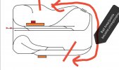
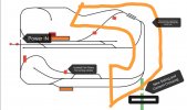
And again, after a perfect 20 minutes it starts again. But, I think I have narrowed the problem down. The points only become unresponsive when the locomotive is on a one half of the circuit, and it always seems to be the same area onnthe circuit. I cannot get the points to not work when the train is on the other half, which is incidentally the half that the track power enters the track. So, could it be as simple as some failing fish plates which have just been pushed a little too far with the adition of the new siding/LC which as it happens spurs off the half of the circuit where the points fail when the train is in that 'bad' half?
 

duncan1_9_8_4

Jack of all trades on the Railway
25 Oct 2009
3,302
504
40
Pontefract, West Yorkshire
Best answers
0
Country flag
Does your new "level crossing" include any electrically operated gates, lights, etc. powered by the CS3?
No mate, the other half drew the line at such fancy things.
 

duncan1_9_8_4

Jack of all trades on the Railway
25 Oct 2009
3,302
504
40
Pontefract, West Yorkshire
Best answers
0
Country flag
IMG_20210818_092329.jpg
 

mike

Master at annoying..
Staff member
GSC Moderator
24 Oct 2009
51,805
4,433
Rossendale
www.gscalecentral.net
Best answers
0
Country flag
Get a test section on track..disconnect the cs3 ,from the railway..connect to test track..run locos on test track...if they run OK...its not the locos...add a point and drive unint...dose the problem surface?...
It could be your track needs clamps,and /or more power feeds ?
 

phils2um

Phil S
11 Sep 2015
1,522
423
Ann Arbor, Michigan
Country
United-States
Best answers
0
Country flag
You have two reverse loops. Where are they isolated (location of the insulating joiners)? What sections are having their polarity swapped by the reverse-loop modules? Where is track power coming in? What wire size feeder is there from the CS3 to the rails? Where is the level crossing and did you add any new track when you put it in?
 

dunnyrail

DOGS, Garden Railways, Steam Trains, Jive Dancing,
Staff member
GSC Moderator
25 Oct 2009
26,164
4,989
75
St.Neots Cambridgeshire UK
Best answers
0
Country flag
One assumes that you have made provision for reverse loop modules and that neither of those 2 reverse loops are causing issues?
 

duncan1_9_8_4

Jack of all trades on the Railway
25 Oct 2009
3,302
504
40
Pontefract, West Yorkshire
Best answers
0
Country flag
One assumes that you have made provision for reverse loop modules and that neither of those 2 reverse loops are causing issues?
The reverse loops have been there for best part of a year without issue now. Definitely starting to think it could be a combination of failing joints.
 

duncan1_9_8_4

Jack of all trades on the Railway
25 Oct 2009
3,302
504
40
Pontefract, West Yorkshire
Best answers
0
Country flag
You have two reverse loops. Where are they isolated (location of the insulating joiners)? What sections are having their polarity swapped by the reverse-loop modules? Where is track power coming in? What wire size feeder is there from the CS3 to the rails? Where is the level crossing and did you add any new track when you put it in?
IMG_20210818_101729.jpg
 

jimmielx

45mm gauge track - approx 16mm scale (1:19)
24 Oct 2009
786
41
Hastings, UK
Country
United-Kingdom
Best answers
0
Country flag
Failing joints are indeed a very likely cause of problems. Almost always the problems I get of this nature are with rail joints - they do have a tendency to go away again, but fear not, they will continue to reappear until remedied! You mention that you are using fishplates. I would suggest that those are very likely to fail in time. For reliable conductivity in the long term I would recommend Massoth Rail Clamps.
Alternatively you could solder jumpers across the rail joints, though soldering to G scale rail can be tricky.
Assuming that your layout is all on fishplates, I'd get a stock of joiners in and replace the fishplates as they become problematic.
I would also consider putting additional feeders from the CS3 in around the track. This will help enormously.

The current draw readings you mentioned about look fine to me. It would be worth establishing the maximum current your system can provide. The CS3 is capable of providing 5A, but only if used with a higher rated power supply. From the documentation I have seen online it seems that the power supply that comes with the CS3 as standard is only capable of supplying 3A. Assuming that's what you have, it does seem sufficient for you present needs, but at least you have a potential easy route to increase current capacity as your empire expands.
 

duncan1_9_8_4

Jack of all trades on the Railway
25 Oct 2009
3,302
504
40
Pontefract, West Yorkshire
Best answers
0
Country flag
Failing joints are indeed a very likely cause of problems. Almost always the problems I get of this nature are with rail joints - they do have a tendency to go away again, but fear not, they will continue to reappear until remedied! You mention that you are using fishplates. I would suggest that those are very likely to fail in time. For reliable conductivity in the long term I would recommend Massoth Rail Clamps.
Alternatively you could solder jumpers across the rail joints, though soldering to G scale rail can be tricky.
Assuming that your layout is all on fishplates, I'd get a stock of joiners in and replace the fishplates as they become problematic.
I would also consider putting additional feeders from the CS3 in around the track. This will help enormously.

The current draw readings you mentioned about look fine to me. It would be worth establishing the maximum current your system can provide. The CS3 is capable of providing 5A, but only if used with a higher rated power supply. From the documentation I have seen online it seems that the power supply that comes with the CS3 as standard is only capable of supplying 3A. Assuming that's what you have, it does seem sufficient for you present needs, but at least you have a potential easy route to increase current capacity as your empire expands.
Thanks for that. I have slowly been replacing dodgy fish plates with the brilliant massoth Clamps. Ran out at present though. The power supply is a Marklin 60101 as supplied by the model shop. I shall get some more Clamps.