CS3 Problems

phils2um

Phil S
11 Sep 2015
1,522
423
Ann Arbor, Michigan
Country
United-States
Best answers
0
Country flag
0.58 amps seems pretty high for no train on the track. Your three switch decoder modules and two reverse-loop modules only consume 20 - 30 mA each. That's 0.2 A max being very generous. What's eating up the other 0.4 amps?

To give some perspective I've got 2 x LGB 4 ch switch decoders, 2 x Massoth 4ch switch decoders, 4 x LGB single ch switch decoders, 1 x MD Electronics single ch switch decoder, 1 x LGB reverse-loop module, and 14 x 0.013A LEDs powered when no trains are on the track. My total amperage is 0.42A
 

jimmielx

45mm gauge track - approx 16mm scale (1:19)
24 Oct 2009
786
41
Hastings, UK
Country
United-Kingdom
Best answers
0
Country flag
Happily, the 60101 power supply will give you the maximum 5A current supply from the CS3.
 

phils2um

Phil S
11 Sep 2015
1,522
423
Ann Arbor, Michigan
Country
United-States
Best answers
0
Country flag
You might try putting in a temporary jumper to feed power to the region where you are having trouble in addition to your original feed to see if that helps. But I suspect it may be a problem with the joiners too.
 

AlanL

Registered
1 Mar 2016
146
19
Northampton
Best answers
0
Country flag
Going back to your original question about cement causing a problem. Many years ago when I created a full-size level crossing I discovered that it was creating some current leakage through the new mortar. I waited a couple of days for it to improve and finally in panic I ripped it out and re-laid the mortar. The second attempt was successful, the difference was that with the first attempt the mortar had the addition of plasticiser and the second attempt was used without any additives. My railway at the time was a very small and simple oval. I had no other complications, components to doubt that the mortar was causing a problem. Perhaps the mortar with additive would have dried properly over time but I couldn't wait to find out.

The stand-by current on your controller does seem high, it would be interesting to break up your rail connections to identify where the current is being taken. Some people advocate having the railway divided into separate electrical sections with individual feeders for such fault-finding. I have only one feed to the track-work but I do have 100% rail-joiners and by removing joiners I can locate faults.

Could you dis-connect electrically the level crossing area by removing the rail-joiners/fishplates?

As you have one power feed to the track consider removing a pair of rail connectors around the centre section. If you find that there is no power on one side of the break it means that you definitely have a bad rail connection.

As other posters have suggested, your main problem is probably an accumulation of poor rail connections that are strangling the current on that side of your layout.

Good luck

Alan
 

dunnyrail

DOGS, Garden Railways, Steam Trains, Jive Dancing,
Staff member
GSC Moderator
25 Oct 2009
26,209
4,998
75
St.Neots Cambridgeshire UK
Best answers
0
Country flag
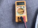
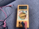
A further thought, if you have a small test meter it is worth testing each rail joint. Each one should show the same result as when you touch the 2 leads together Ie 0 or infinite. Any other result say a number (.5 for example) rather than 0 would suggest that the joint is less than perfect. Though this method may not be 100%, it would indeed show any that are suspect. A result of 1.0 would suggest no juice is getting past the joint, this being the number before terminals are touched. Appologies if I appear to be teaching Granny how to suck eggs, but often the obvious is easily missed.EDIT just in case it os not obvious, do 1 rail then the other side. I would be tempted to do a rough diagram showing every joint and mark them up as you test each one. A colour scheme could be used to indicate any Clamps you have fitted. This would come in handy in the future as you may decide to add more clamps or indeed do some bonding. Many talk about bonding being tricky to do, but if you bond only using the webb of the rail there is less to head up and the process is simpler and of course cheeper than clamps.
image.jpgimage.jpg
 
Last edited:

duncan1_9_8_4

Jack of all trades on the Railway
25 Oct 2009
3,314
508
40
Pontefract, West Yorkshire
Best answers
0
Country flag
Update, I found 12 massoth rail clamps, and I have used them all on the area that where a train was passing through, I lost control of the points.

Before I did this, the power read;
Current - main track 0.583 A (with no trains moving)

After doing the fish plates and tightening existing ones around the circuit it now reads;

Current - main track 0.475 (with no locomotive running)

So doing some fish plates with clamps appears to have made a small difference to the reliability of the circuit?

As I run at the moment, the points seem fine. But I am going to order some more clamps and slowly work my way through the entire layout, once my finger ends repair. I reckon 2/3 of the layout still need clamps.

Its interesting how dirty the inside of the fish plates and rail get, no wonder connectivity deteriorated. I shall keep you all updated.

Once again, thank you ALL for your help and input. I feel a lot better about it this afternoon compared to 2345 last night.
 
  • Like
Reactions: 1 user
8 Mar 2014
7,806
972
San Diego
Country
Armenia
www.elmassian.com
Best answers
0
Country flag
So your posts seemed to imply that none of the points worked when you "lost control".... are they all connected to the same point in the track, and how many?

It now sounds like it is isolated to an area of bad conductivity, not just add a loco anywhere and all the points stop. (which would imply overload).

Greg
 

JimmyB

Now retired - trains and fishing
23 Feb 2018
6,959
925
69
Weston-super-Mare
www.tumble-down-falls.co.uk
Best answers
0
Country flag
Update, I found 12 massoth rail clamps, and I have used them all on the area that where a train was passing through, I lost control of the points.

Before I did this, the power read;
Current - main track 0.583 A (with no trains moving)

After doing the fish plates and tightening existing ones around the circuit it now reads;

Current - main track 0.475 (with no locomotive running)

So doing some fish plates with clamps appears to have made a small difference to the reliability of the circuit?

As I run at the moment, the points seem fine. But I am going to order some more clamps and slowly work my way through the entire layout, once my finger ends repair. I reckon 2/3 of the layout still need clamps.

Its interesting how dirty the inside of the fish plates and rail get, no wonder connectivity deteriorated. I shall keep you all updated.

Once again, thank you ALL for your help and input. I feel a lot better about it this afternoon compared to 2345 last night.
You seem to have found the solution. or at least part of it "connectivity".
It has been said a number of times on this site about connections between track, whether clamps or bonded rails, that the standard fishplates are not up to the job and will fail, and cause issues. This has been an objective lesson, and I hope other will learn from you - well done :)
 
  • Like
Reactions: 1 user

duncan1_9_8_4

Jack of all trades on the Railway
25 Oct 2009
3,314
508
40
Pontefract, West Yorkshire
Best answers
0
Country flag
So your posts seemed to imply that none of the points worked when you "lost control".... are they all connected to the same point in the track, and how many?

It now sounds like it is isolated to an area of bad conductivity, not just add a loco anywhere and all the points stop. (which would imply overload).

Greg
They are all connected at different points around the circuit, to stop unnecessary long runs of wire to get to points a long way from where they would be if they were all together. It's just as if when a locomotive was passing between what must have been two bad joins, but a distance apart, it was somehow making the power drain too much to throw the points, because if I stopped the locomotive in the bad section between the bad joins, the power then threw the points. I find ot hard to explain.
 

phils2um

Phil S
11 Sep 2015
1,522
423
Ann Arbor, Michigan
Country
United-States
Best answers
0
Country flag
I'm not sure exactly what goes on with the CS3 when it nears an overload condition but not enough to trip. Mine will behave the same way as Duncan's, the digital encoding gets corrupted to the point where some decoders no longer recognize the signal. In my case ESU decoder equipped locos in particular would just continue merrily on with their previous setting as if encountering an analog section and could not be controlled, This is in addition to the point decoder issue. Also, the temperature of the booster climbs markedly. I've seen mine get close to 80ºC in the past! And you can watch it climb! My CS3 internal booster usually runs around 45ºC when all is right. My add-on Märklin 60175 booster runs about 35ºC normally.
 

duncan1_9_8_4

Jack of all trades on the Railway
25 Oct 2009
3,314
508
40
Pontefract, West Yorkshire
Best answers
0
Country flag
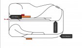
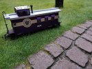
Another discovery. When I put my USA trains caboose on the line, with its interior and exterior lights on, it stops points working off module 1 and 2. But 3 works fine. Take it off or switch its lights off, the points work fine again. This is whilst running the 4 wheel lgb schoma diesel. This is when the caboose is on the small circuit, near module 2 for example. Looks like more fish plate work on the small inner circuit. IMG_20210818_203516.jpgIMG_20210818_202606.jpg
 

duncan1_9_8_4

Jack of all trades on the Railway
25 Oct 2009
3,314
508
40
Pontefract, West Yorkshire
Best answers
0
Country flag
8 Mar 2014
7,806
972
San Diego
Country
Armenia
www.elmassian.com
Best answers
0
Country flag
This is all over the place.

The bad joiners were a lack of conductivity, not an overload.

Now it appears that you only have a problem at a certain place, reading between the lines, not all points as inferred by the original post.

I'm giving my last advice here, because there are so many theories abounding you could spend years trying them.

My suggestions are to find the shortest, quickest, and most deterministic path to the answer.

It now appears you have conductivity problems, but also the prior comments about current draw hold, i.e. you should check that the current drawn with nothing on the layout makes sense with the number of point decoders that are attached.

Debugging bad "fishplates" takes a different technique, if you do not want to make a career of it.


This is my best, well thought out, deterministic suggestion.

Greg
 

AlanL

Registered
1 Mar 2016
146
19
Northampton
Best answers
0
Country flag
Dunnyrail's suggestion in post #25 will not show you a problem. Because the track is a closed circle, you will get a reading around the far side of the circle even if the joint that you are testing is open circuit (not connected). You would have to break the circle of track to find the high resistance faulty join or most likely, numerous faulty joins.

An accumulation of bad joints will strangle the current available at the rail. Adding the caboose confirms the strangling of current.The reading on the CS3 is irrelevant for the fault except for the unusual high stand-by current. The current draw showing on the CS3 when your problems occur are well within it's output.

Replacing the fishplates with clamps will be your best solution.

Good luck

Alan
 

duncan1_9_8_4

Jack of all trades on the Railway
25 Oct 2009
3,314
508
40
Pontefract, West Yorkshire
Best answers
0
Country flag
Dunnyrail's suggestion in post #25 will not show you a problem. Because the track is a closed circle, you will get a reading around the far side of the circle even if the joint that you are testing is open circuit (not connected). You would have to break the circle of track to find the high resistance faulty join or most likely, numerous faulty joins.

An accumulation of bad joints will strangle the current available at the rail. Adding the caboose confirms the strangling of current.The reading on the CS3 is irrelevant for the fault except for the unusual high stand-by current. The current draw showing on the CS3 when your problems occur are well within it's output.

Replacing the fishplates with clamps will be your best solution.

Good luck

Alan
I shall keep you informed. Thanks fornthe reply.
 
8 Mar 2014
7,806
972
San Diego
Country
Armenia
www.elmassian.com
Best answers
0
Country flag
For the few that read my link, I call the "circle" problem the "clock" problem so people can visualize how it's often multiple connections/failures and a loop that makes it more difficult to visualize and understand, just as Alan states.

For the record, I break my track into competely insulated blocks, powered from the approximate center. When I have an issue, I can easily isolate that part of track, and since it is not a circle, the bad joiners/connections are easy to find and debug. It takes a bit more wire, and you need to keep your connections "better", but the payoff of almost instant location of bad joiners is definitely worth it to me.

Greg
 

duncan1_9_8_4

Jack of all trades on the Railway
25 Oct 2009
3,314
508
40
Pontefract, West Yorkshire
Best answers
0
Country flag
For the few that read my link, I call the "circle" problem the "clock" problem so people can visualize how it's often multiple connections/failures and a loop that makes it more difficult to visualize and understand, just as Alan states.

For the record, I break my track into competely insulated blocks, powered from the approximate center. When I have an issue, I can easily isolate that part of track, and since it is not a circle, the bad joiners/connections are easy to find and debug. It takes a bit more wire, and you need to keep your connections "better", but the payoff of almost instant location of bad joiners is definitely worth it to me.

Greg
I had a good read of your very well written article. I will be acting on its advice come my next day off, thanks for writing it and sharing it. For the next few days though, the real railway beckons.
 
8 Mar 2014
7,806
972
San Diego
Country
Armenia
www.elmassian.com
Best answers
0
Country flag
So 0.475 amps for 3 point motor decoders and 2 reverse modules So, given the accuracy of the current measuring system. Under 100 ma per device does not sound so bad, but I have to respect the comment by Phil.

Does anyone have any reference data to support this (or counter it)?

Greg