Battery Conversion of a Ten Wheeler

JimmyB

Now retired - trains and fishing
Country flag
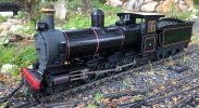
I know I have made mention of my conversion of an old Bachmann Battery RC locomotive to a modern 2.4 GHz with LiPo batteries.
The loco and tender are all stripped down, and new "Annie" chassis, with metal wheel and metal valve gear has been acquired, so I was looking to put the electronics together:
Deltang Rx66a
MLS sound
Outlander 3C, 2200 mha LiPo Battery.

As per my Stainz and and Otto conversions I am using a plug-in curcuit board to keep wire splicing to a minimum and fault diagnosis easy.

Loco connected to the battery and Rx, binding complete and it works (why wouldn't it)
So yesterday made the leads for the MLS, and guess what, nothing works. Then I had sound, then nothing, foolish me, connected the power out to the chuff sensor and not the power connection on the loco, so loco is okay. Still problems with the sound, all the connections tested, and power there but sometimes sound sometimes none.
Out with the MLS booklet, and there was the answer, bench testing with a bright light, puts the MLS in programming mode, light off and it works:

10-Wheeler-elecs.jpg
 
If all else fails a look at the manual generally assists to the right result, but you do know that is cheating?
 
Well done on reading our instructions.

Just one tip, I used the same chassis to make the loco in the attached photo. The result was that it pulls very little. It is too light and the two driving axles which actually touch the rails just slip. Therefore, while you have the loco in bits, you need to add lead weight wherever you can.

Regards
Peter Lucas
MyLocoSound
 

Attachments

  • MyYx.jpg
    MyYx.jpg
    1 MB · Views: 0
As per my Stainz and and Otto conversions I am using a plug-in curcuit board to keep wire splicing to a minimum and fault diagnosis easy.

View attachment 272294
Jimmy be interested to see a pic of the other side of your Veroboard Plug setup, that is if you have not sealed it inside by now.
 
dunnyrail dunnyrail just a simple set of connection, a row of 2 pin JST-XH sockets for the motor, i.e. Rx out, motor in and MLS in, a row of 3 pin JST-XH scokets for power, i.e. battery (via switch) in Rx in and MLS in, positive on the outside, negative on the inside, and the centre for the LED 2 which is part of the switch. Having 2/3 pin socked means I cannot get them the wrong was around. If I needed additional slices I would factor in more sockets. I do not take my front light from LED 2, but off the motor, and using a bi-coloured LED I can have white going forward and red in reverse.

Veroboard.jpg
 
dunnyrail dunnyrail just a simple set of connection, a row of 2 pin JST-XH sockets for the motor, i.e. Rx out, motor in and MLS in, a row of 3 pin JST-XH scokets for power, i.e. battery (via switch) in Rx in and MLS in, positive on the outside, negative on the inside, and the centre for the LED 2 which is part of the switch. Having 2/3 pin socked means I cannot get them the wrong was around. If I needed additional slices I would factor in more sockets. I do not take my front light from LED 2, but off the motor, and using a bi-coloured LED I can have white going forward and red in reverse.

View attachment 272394
Thanks Jimmy.
 
Still problems with the sound, all the connections tested, and power there but sometimes sound sometimes none.
We found the MLS boards need a push to get them started. When testing on the bench, I attach a 9V battery (a 'keep alive' for when power is too low to drive the board,) and then touch a wire from the + power-in connector to the 9V +battery. The board thinks someone applied power and took it away, but it starts the sound and keeps it on.
Our problem has been stopping it. The manual says it goes to sleep - we haven't noticed it doing so.
Thinking about what Jimmy says about sounds some time and sometimes not. One of my MLS is a bit like that, have to press the whistle or bell button to get things on the go. There is also a setting that switches sound off after no use for a while created with the TV remote. I wonder if this on/off things is another of the setups?
 
The manual says it goes to sleep - we haven't noticed it doing so.

I think it depends which version you have, as there have been developments along the way.

My first one was a steam card which doesn't go to sleep, but then you can have a Westinghouse Brake sound which needs to stay on for as long as ................ My second card was a diesel which does go to sleep.

I've just installed another diesel, but haven't left the loco on long enough at rest as the second loco I was using was running off the same Tx, so I needed to shut the first one down.

Mine all kick in when you switch 'em on. Just installing a fourth (a steam sound card). Both diesels are battery, both steamers are track powered DC (Bachmann Spectrum) and the voltage the locos require is so low, that you have to use a voltage step-up unit for the sound card to keep the re-chargeable 9v PP3 charged. I set the step-up at 19v as the card will accept up to 24v.
 
The soundcards with a blue PCB which we have produced for the past three years work like this.

To wake up automatically, the soundcard M1/M2 terminals need to be connected to the motor. Then the soundcard will wake up when the tiniest bit of power is applied to the motor via the track or an onboard battery. If you are testing the soundcard on the bench without a motor then connect a 9v battery to the B+ and B- terminals and then touch a wire across from B+ to M1. That will wake up the soundcard and it will keep running.

The soundcard needs to be set to trackpower or battery power, as shown in the instructions section 8, depending on what the loco is using. The soundcard will go to sleep only on trackpower. This is to prevent all charge being lost from the 9v support battery. It does not go to sleep on battery power because there is no reason to do so.

When used with trackpower, the soundcard will automatically recharge the support battery whenever the track voltage exceeds 10v. If your track voltage rarely goes that high then you can use a voltage booster between the motor and the soundcard M1/M2 terminals as Rhinochugger suggests. But, as he says, keep the voltage below 24v.

Regards
Peter Lucas
MyLocosound
Oh yes, and you need a bridge rectifier before the voltage step-up unit. You don't normally need one for the sound card, as Peter's obviously got that covered, but the step-up / step-down units don't like the juice going backwards :oops::oops:
 
Slow progress on the 10-Wheeler during the nice weather, but today I continued with the electronics installation. As previously mentioned this is all going in the tender, and I wanted the charging socket/switch/LED 2 repeater, hidden but easily assessable, and under the rear hatch was the place. Being fussy though I didn't want it fixed to the tender body, which would mean either long wires, or disconnection when the body was removed, so:

A module was produced to hold the assembly:

IMG_0932.jpg

This was then fitted to the chassis:

IMG_0933.JPG

Easy access the the module, just remove the hatch:

IMG_0936.jpg
 
Chuff sensor question:
For those of you familiar with the "Annie" chassis, and the MLS, the rear of the chassis has a two pin socket from the chuff "mechanism" running of the front driving axle, can these be connected to the MLS "Chuff cam trigger", and is so how, as I am not familiar with how this works. Ta :)
 
I believe this is like other Bachmann chassis? - If so, then yes, it is just a 'cam-switch' on the axle.

One wire to 'chuff' the other to ground (neagtive).

PhilP.
 
Back
Top Bottom