Super glue not the best solution for moving metal parts. Accepting this is possibly the only solution, glue on the start of where you push it in and at the start of the hole where you push it in should give it a better chance.Update on the failed V2 signal.
I had forgotten that I had used a brass rod for the blade pivot.
The operating crank inside the signal head and the signal blade were both super glued to the brass rod. The crank part was cut away to allow space for the super glue to hold but the blade was just a plain hole. The problem with a plain hole is that any glue is pushed away as the parts are assembled.
I will repair this signal again with super glue but this time I will grind a flat or 2 flats on the rod to provide a surface for the glue to attatch to.
The V3 version was made with all these components printed as 1 assembly and will not fail in this way (I hope

)
View attachment 343533View attachment 343534
Alan
You are using an out of date browser. It may not display this or other websites correctly.
You should upgrade or use an alternative browser.
You should upgrade or use an alternative browser.
3D Semaphore Signals
- Thread starter AlanL
- Start date
AlanL
Registered
The brass rod was attacked by the dremel cutting disc and now has some digs in it for the glue to stick to.
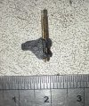
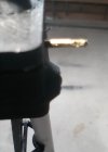
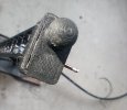
After roughing up the rod, the signal blade is now an interferance fit (possibly due to burrs in the grinding process) and may not need to be glued because it is suitably tight on the brass rod.
If the signal blade takes a knock then I would rather the blade fixing be the weak spot than the tiny internal crank. The crank has a cut away to allow an area for the glue but it is still a small component.
I might revert to this method, using a brass rod, for the next pair of signals. The blade assembly is easier this way.
This signal now needs a new top cover, the original was damaged in the removal process and the signal will be replaced outside to see how it holds up to the weather. I would have liked to inspect the internals in the base while the signal was out but it is so well sealed that it is not easy to get into.
Alan
AlanL
Registered
Latest news on the signals.
After recent heavy rain, a week later I tested both signals and they were both working. However after a second week the V3 version had stopped working, condensation within being the culprit. Happily the earlier V2 version was and still is working.
Time now to develop the fourth version.
As the V2 version was still working and still is despite further heavy rain I decided to continue with the brass rod design as opposed to the all in one printed crank of the V3 version. This also allows me to add some detail such as bolt heads to the blade.
.
Inside the signal head I made the crank with more of a hook. This allowed me to raised the internal barrier slightly.
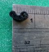
Also I tightened the clearance holes for the brass rod so that rain had less space to enter the signal and added a collar behind the blade to discourage rain to enter the signal head. The signal blades are simply a friction fit on the brass rod and if they endure the weather, birds and the gardener with his big boots this will be my preferred method.
Most of the changes are at the base of the signal.
The first change was to move the servo 3mm lower from the roof of the base. Difficult to illustrate this but previously the servo was tight against the top of the base. This is where the condensation was occurring. By making a 3mm air gap I hoped that it will save the sides of the servo heating up and causing the moisture to condense within the servo case. The whole signal base that sits below ground is now 3mm deeper.
The second change was to introduce some ventilation to the base.
I made a 'cabinet' at the bottom of the signal post. This cabinet has louvres to allow air to enter the base. The louvres have a 1mm gap and aren't fitted with insect mesh so I'm hoping that the ants don't discover it
As before a flat plate was sealed to the base and acts as an anchor when buried.
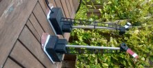 This photo was in portrait mode and flipped itself.
I made 3 of these V4 signals with 2 of them controlling the junction as below.
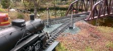
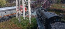
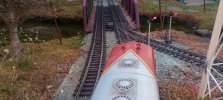
The control system for these signals is in a nearby building.
The V2 version is still working and there are now 3 of the V4 versions installed.
Just need some bad weather now to see how these last.
AL
After recent heavy rain, a week later I tested both signals and they were both working. However after a second week the V3 version had stopped working, condensation within being the culprit. Happily the earlier V2 version was and still is working.
Time now to develop the fourth version.
As the V2 version was still working and still is despite further heavy rain I decided to continue with the brass rod design as opposed to the all in one printed crank of the V3 version. This also allows me to add some detail such as bolt heads to the blade.
.
Inside the signal head I made the crank with more of a hook. This allowed me to raised the internal barrier slightly.

Also I tightened the clearance holes for the brass rod so that rain had less space to enter the signal and added a collar behind the blade to discourage rain to enter the signal head. The signal blades are simply a friction fit on the brass rod and if they endure the weather, birds and the gardener with his big boots this will be my preferred method.
Most of the changes are at the base of the signal.
The first change was to move the servo 3mm lower from the roof of the base. Difficult to illustrate this but previously the servo was tight against the top of the base. This is where the condensation was occurring. By making a 3mm air gap I hoped that it will save the sides of the servo heating up and causing the moisture to condense within the servo case. The whole signal base that sits below ground is now 3mm deeper.
The second change was to introduce some ventilation to the base.
I made a 'cabinet' at the bottom of the signal post. This cabinet has louvres to allow air to enter the base. The louvres have a 1mm gap and aren't fitted with insect mesh so I'm hoping that the ants don't discover it
As before a flat plate was sealed to the base and acts as an anchor when buried.
 This photo was in portrait mode and flipped itself.
I made 3 of these V4 signals with 2 of them controlling the junction as below.


The control system for these signals is in a nearby building.
The V2 version is still working and there are now 3 of the V4 versions installed.
Just need some bad weather now to see how these last.
AL
AlanL
Registered
Yes they do and there is not a lot of room. I'm using aluminium tube for the post of 6 mm diameter with an inside diameter of 4 mm. The control rod that is 0.6 mm piano wire when bent to a right angle is almost 4 mm at it's top end inside the signal head.Alan are you running your control rods up inside the post
In the photos below there is an old rejected control rod that was cut too short to reliably operate the crank arm, it does not protrude from the crank.
I bend this to a right angle first to a generous length and then cut to about 3 mm after bending.
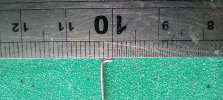
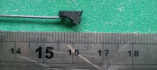
An old version showing the operating hole for the control rod.
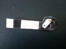
And another old photo inside the signal head that just shows the top of the control rod and the lack of space.
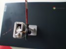
Al
GAP
G Scale Model Trains, 1:1 Sugar Cane Trains
Thanks for the pictures.
What I'm thinking about is 2 control rods onside the post.
I'm going to have 2 blades per post and was going to use the 3D posts you sent me.
Bit of thinking is going to have to be done.
Might have to put the rods on the outside.
What I'm thinking about is 2 control rods onside the post.
I'm going to have 2 blades per post and was going to use the 3D posts you sent me.
Bit of thinking is going to have to be done.
Might have to put the rods on the outside.
AlanL
Registered
Yes there would no room for 2 control rods in this signal. These signals are based on a motorised head that does not operate using mechanical links. Using 2 control rods for 2 signals outside the post is a typical method in the real world.Might have to put the rods on the outside.
You need to devise a method of mounting 2 servos and a linkage to operate the signals. Perhaps get some ideas from the RC aeroplane world with their large choice of linkage components.
AL
GAP
G Scale Model Trains, 1:1 Sugar Cane Trains
I'm going to use 1 servo with a circular actuator.
The way my signalling is going to work is 2 arms on the one post one above the other, when straight through the upper arm is lowered and the lower is horizontal, when points change the upper arm is pushed to horizontal and the lower is dragged down to an angle.
Probably not conventional but will give an indication of point setting from a distance, top will be red and lower will be yellow/orange.
The signal servo will be "point following"driven by an output from the point controller.
Rods on the outside look like the design way to go.
Indeed indication of point setting not normal practice other than when giving access to the route. However on my line I have 3 signals that specifically are to indicate the setting of a point thus Rule 1 applies here.I'm going to use 1 servo with a circular actuator.
The way my signalling is going to work is 2 arms on the one post one above the other, when straight through the upper arm is lowered and the lower is horizontal, when points change the upper arm is pushed to horizontal and the lower is dragged down to an angle.
Probably not conventional but will give an indication of point setting from a distance, top will be red and lower will be yellow/orange.
The signal servo will be "point following"driven by an output from the point controller.
Rods on the outside look like the design way to go.
GAP
G Scale Model Trains, 1:1 Sugar Cane Trains
Yep on part of the layout the position of the point lever is a visual of the setting.Indeed indication of point setting not normal practice other than when giving access to the route. However on my line I have 3 signals that specifically are to indicate the setting of a point thus Rule 1 applies here.
But I have also gone all High Tech and have a computer program that shows the point setting on a monitor as well so I can see at a glance the setting out around the layout.
