AlanL
Registered
Time for an update on the signals that were installed last year.
First the bad news. Out of the 4 signals only 1 remained working after the damp winter.
The good news is that all of the newer versions did not have any moisture in them. The single older version had a fair bit of moisture in its base. So I am pleased that the changes that I made to drain moisture at the top of the signals have worked. This was the first prerequisite of the signals, not to fill up with water.
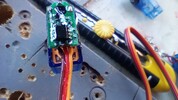
Some of the servos had signs of condensation on the inside of their cases -


Users of servos in radio controlled models are concerned about using them in the rain and protection against splashes. After their use outdoors they are stored in a dry and stable environment.
In the railway garden we want to leave the servos outside 24/7 where they are subject to extremes of temperature and the rapid warming by sunshine. This rapid warming leads to condensation and is a cause of failure.
There are a lot of ideas and materials for waterproofing servos but they are for applications that are concerned about direct slashes of water and they don't have the issue of leaving their models outdoors 24/7.
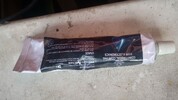
Looking at waterproofing products I came across a material called "Conformal Coating". There is a selection of materials, including acrylic, resin and silicone. They all work by being of low viscosity that easily flows and sets to protect PCB's from damage. The silicone version makes a thick, flexible covering to give excellent protection from moisture. They are made to waterproof circuit boards, the ideal solution for outdoor servos.
I ordered the silicone in a tube. Conformal Coating
.jpg")
To apply the Conformal Coating, I had to dismantle the servos.
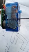
Removing the tiny screws, the top cover comes off, exposing the circuit board and also the bottom cover with the gears.
This left the centre section that contained the motor and potentiometer -

The top cover in this photo has holes in it's sides, I am trying out ventilation fitted to a pair of servos as a test.
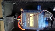
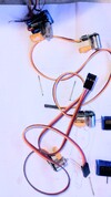
Then I had to remove the motor, circuit board and potentiometer from the centre case.
These are a tight fit in the casing but pressed out by pushing a screwdriver flat on the tiny gear and a smaller screwdriver to ease out the orange tabs of the potentiometer -


Note the signs of a rusty motor in the photos above. This is the servo removed from the early signal version that contained a lot of moisture.
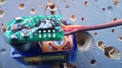
I prepared 4 servo boards to be coated avoiding the potentiometers. The top one is removed from the last working signal -

The Conformal coating was then applied straight from the nozzle covering both sides of the circuit board. The gel flows readily over the components and left a smooth self levelling layer over the board. It is totally transparent and can only be seen by the light reflecting off the gel -


The boards were covered so effectively that I think that they could be immersed in water and still work, especially if a second coat were applied for security.
I will now re-assemble the 4 signals and return them to their places for another 12 months feeling optimistic about their chances of survival.
In the meantime I have some more signals to make for other locations around the railway")
Alan
First the bad news. Out of the 4 signals only 1 remained working after the damp winter.
The good news is that all of the newer versions did not have any moisture in them. The single older version had a fair bit of moisture in its base. So I am pleased that the changes that I made to drain moisture at the top of the signals have worked. This was the first prerequisite of the signals, not to fill up with water.
Some of the servos had signs of condensation on the inside of their cases -
Users of servos in radio controlled models are concerned about using them in the rain and protection against splashes. After their use outdoors they are stored in a dry and stable environment.
In the railway garden we want to leave the servos outside 24/7 where they are subject to extremes of temperature and the rapid warming by sunshine. This rapid warming leads to condensation and is a cause of failure.
There are a lot of ideas and materials for waterproofing servos but they are for applications that are concerned about direct slashes of water and they don't have the issue of leaving their models outdoors 24/7.
Looking at waterproofing products I came across a material called "Conformal Coating". There is a selection of materials, including acrylic, resin and silicone. They all work by being of low viscosity that easily flows and sets to protect PCB's from damage. The silicone version makes a thick, flexible covering to give excellent protection from moisture. They are made to waterproof circuit boards, the ideal solution for outdoor servos.
I ordered the silicone in a tube. Conformal Coating
To apply the Conformal Coating, I had to dismantle the servos.
Removing the tiny screws, the top cover comes off, exposing the circuit board and also the bottom cover with the gears.
This left the centre section that contained the motor and potentiometer -
The top cover in this photo has holes in it's sides, I am trying out ventilation fitted to a pair of servos as a test.
Then I had to remove the motor, circuit board and potentiometer from the centre case.
These are a tight fit in the casing but pressed out by pushing a screwdriver flat on the tiny gear and a smaller screwdriver to ease out the orange tabs of the potentiometer -
Note the signs of a rusty motor in the photos above. This is the servo removed from the early signal version that contained a lot of moisture.
I prepared 4 servo boards to be coated avoiding the potentiometers. The top one is removed from the last working signal -
The Conformal coating was then applied straight from the nozzle covering both sides of the circuit board. The gel flows readily over the components and left a smooth self levelling layer over the board. It is totally transparent and can only be seen by the light reflecting off the gel -
The boards were covered so effectively that I think that they could be immersed in water and still work, especially if a second coat were applied for security.
I will now re-assemble the 4 signals and return them to their places for another 12 months feeling optimistic about their chances of survival.
In the meantime I have some more signals to make for other locations around the railway
Alan


 . I think the problem is condensation due to sunshine heating a small enclosure such as a servo case.
  so didn't bother.Using the thicker gel type product you can see the coverage with the thickness of the coating rather than a thin spray coat.