What happened at your workbench today?

maxi-model

UK/US/ROW steam narrow gauge railways 1:1
27 Oct 2009
5,673
661
Bucks/Oxon/Northants area
Best answers
0
Country flag
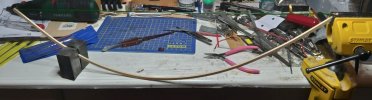
Cute , eh ? My little dinky Porter now has it's own dinky little tender. The only one with one on the West Well Lumber Co. roster. Max

20210723_081929.jpg20210723_081836.jpg20210723_081812.jpg
 
  • Like
Reactions: 1 users

dunnyrail

DOGS, Garden Railways, Steam Trains, Jive Dancing,
Staff member
GSC Moderator
25 Oct 2009
26,076
4,976
75
St.Neots Cambridgeshire UK
Best answers
0
Country flag
Twas a bit cooler today so got on with getting things ready to get the Gause 3 Steam Tram running and also cut the Boiler Tube. Possibly a little large but all the control gear will go inside with the batteries either side.
6B2A7321-D356-4D49-AB13-E6155A8D4ADF.jpeg
Not sure how many are thinking of going Battery powered, I have done this before but worthwhile again showing how the Fosworks Stuff goes together with a My Locosound Card (MLS). Virtually all plug and play, only soldering was the two battery packs together, lead for the motor which made those Plug and Play then screw wire into fittings for the speaker sound functions from a RC 3 wire plug and the controller to the MLS.
16AF2D10-4739-40F7-88C1-98B588FC93F6.jpeg
Return of the sun cause play to stop but managed to change the sound functions to my requirements and get the chuff rate sorted even if you cannot see the wheels. It is stillworth while getting 4 beats to the revolution for a satisfactory chuff rate when running.
 

dunnyrail

DOGS, Garden Railways, Steam Trains, Jive Dancing,
Staff member
GSC Moderator
25 Oct 2009
26,076
4,976
75
St.Neots Cambridgeshire UK
Best answers
0
Country flag

LGB-Sid

Registered
19 Sep 2016
2,036
1,130
65
UK
Best answers
0
Country flag
Or make the centre wheelset flangeless.

In theory ............ if your con rods use the same hole pattern as the Piko ones, then the remaining differences are cosmetic ..... except

Is there a clearance problem at the back end of the slide bar ? I did have that issue on a scratch-built loco :nod::nod:

I swapped the running gear off William Wallace and put it on Grumpy Bear and it runs perfect so it's not a printing problem with the rods etc. , so it's open the Gearbox time I thnk and see if something is wrong inside it
 

LGB-Sid

Registered
19 Sep 2016
2,036
1,130
65
UK
Best answers
0
Country flag
Think I have found the problem with WW gearbox the lid on these have two screws only when you get them but four screw holes I added the other two. It looks like one of the original was screwed in to tight and partially stripped the thread so the lid was lose in one corner, looking at the Gear that meshes with the motor brass Gear it looks a bit stripped on a few teeth which would explain why the con rods go tight some times the motor has lifted enough for the gears to jump hence the damage to the Plastic gears and the connecting rods jamming. All just a guess but will buy new gears, I have already fitted a longer screw in the one that works lose. Ignore the pick up strip that is not runni9ng on the bearing in the pic it was, just the bearing moves when the cover is off.

Just got to work out which Mogul the box was off to buy the gears for it now.

gears.jpg
 
  • Like
Reactions: 1 user

3 minutes of fame

3d printing, electronics and trams
14 Dec 2020
573
154
Lincolnshire
www.mgnr.uk
Best answers
0
Country flag
I would imagine the misalignment in the con rods has caused damage to the gears rather than vice versa.

Check where the tightness occurs and on which wheel. Chances are the distance between the wheel mounting bosses is slightly different to the rod length and this is causing the binding. Ease the hole out on the rod to give a little bit of free play.
 

LGB-Sid

Registered
19 Sep 2016
2,036
1,130
65
UK
Best answers
0
Country flag
I would imagine the misalignment in the con rods has caused damage to the gears rather than vice versa.

Check where the tightness occurs and on which wheel. Chances are the distance between the wheel mounting bosses is slightly different to the rod length and this is causing the binding. Ease the hole out on the rod to give a little bit of free play.
I fitted the running gear off this one, to my other 0-6-0 and it runs perfect with the gear / rods off this box , so I don't believe there is anything different with the rods compared to the first one I made. Hence removing the gearbox and looking for what else is wrong. The tightness is on the front set of wheels but not every rev but when the gear has jumped a tooth or two then the rods will bind and lock. The set of con rods off this one are still on the other 0-6-0 as they run perfect then theirs no point in swapping them back .

Found the gears now on order you just need the Red mogul ones simples :)
 

Paul M

Registered
25 Oct 2016
11,784
1,686
60
Royston
Best answers
0
Country flag
Think I have found the problem with WW gearbox the lid on these have two screws only when you get them but four screw holes I added the other two. It looks like one of the original was screwed in to tight and partially stripped the thread so the lid was lose in one corner, looking at the Gear that meshes with the motor brass Gear it looks a bit stripped on a few teeth which would explain why the con rods go tight some times the motor has lifted enough for the gears to jump hence the damage to the Plastic gears and the connecting rods jamming. All just a guess but will buy new gears, I have already fitted a longer screw in the one that works lose. Ignore the pick up strip that is not runni9ng on the bearing in the pic it was, just the bearing moves when the cover is off.

Just got to work out which Mogul the box was off to buy the gears for it now.

View attachment 288177
Is it just the picture, or is the middle axle missing something on the bottom wheel?
 

LGB-Sid

Registered
19 Sep 2016
2,036
1,130
65
UK
Best answers
0
Country flag
Is it just the picture, or is the middle axle missing something on the bottom wheel?
I assume its just the pic , the middle wheels just float no physical drive to them only via the con rods
 

PhilP

G Scale, 7/8th's, Electronics
5 Jun 2013
33,455
3,504
Nottingham
Best answers
0
Country flag
I assume its just the pic , the middle wheels just float no physical drive to them only via the con rods
I think he means the apparent bare grey section? - I assumed that the motion fitted there?

PhilP
 

Paul M

Registered
25 Oct 2016
11,784
1,686
60
Royston
Best answers
0
Country flag
I assume its just the pic , the middle wheels just float no physical drive to them only via the con rods
Above the red spacer looks like a nice big bearing on the bottom I can't see it, projust the camera angle
 

3 minutes of fame

3d printing, electronics and trams
14 Dec 2020
573
154
Lincolnshire
www.mgnr.uk
Best answers
0
Country flag
Looking at the picture, is the plastic sleeve under the gear the only thing holding the wheel quartering in the correct position? I'm wondering if this is allowing the quartering to be thrown out, causing the binding and gearbox damage?
 

LGB-Sid

Registered
19 Sep 2016
2,036
1,130
65
UK
Best answers
0
Country flag
Looking at the picture, is the plastic sleeve under the gear the only thing holding the wheel quartering in the correct position? I'm wondering if this is allowing the quartering to be thrown out, causing the binding and gearbox damage?
The center set of wheels are totally free as a pair to turn on there own, with quite a lot of sideways movement as well to allow cornering, So the only thing that holds them in line with the quartering and turns them is the con rods, I have never looked how LGB do this on blocks with more than two axles, but I can see why its common for the the centre Piko pin that holds the con rod on to shear as it did on the Piko BR80 I have, twice now. The red plastic sleeve on that axle is to limit the sideways movement I guess ?
 

Paul M

Registered
25 Oct 2016
11,784
1,686
60
Royston
Best answers
0
Country flag
Above the red spacer looks like a nice big bearing on the bottom I can't see it, projust the camera angle
16273001872872529421346653098298~2.jpg
Probably the photo, but looks like there is something different in the bigger circle
 

Madman

Registered
25 Oct 2009
17,068
2,935
Pennsylvania, USA
Best answers
0
Country flag
Good Day All.
 

3 minutes of fame

3d printing, electronics and trams
14 Dec 2020
573
154
Lincolnshire
www.mgnr.uk
Best answers
0
Country flag
View attachment 288204
Probably the photo, but looks like there is something different in the bigger circle
Agreed. If the centre axle is fully floating, this can put a lot more strain onto the con rods, as they are essentially holding the wheel into position, while still transmitting power to the 3rd set - out of sight here.

It seems strange that there's such a large imbalance between the bushing on either side of the centre wheel set.

Can you compare this to your working loco?
 

LGB-Sid

Registered
19 Sep 2016
2,036
1,130
65
UK
Best answers
0
Country flag
View attachment 288204
Probably the photo, but looks like there is something different in the bigger circle
I see what you mean now , the center axle doesn't have any bushes, it's just the axle itself that sits in a vertical slot in the casing just the outher two axles have bearings and both are then driven from the motor, I did look at the centre red sleeve over the axle and all it does is limit the sideways movement of that axle, does this image explain it better.

box2.jpg
 

3 minutes of fame

3d printing, electronics and trams
14 Dec 2020
573
154
Lincolnshire
www.mgnr.uk
Best answers
0
Country flag
Aha, motor drive at both ends?

In which case, I agree, the damaged gearbox most likely is causing the binding, as the con rods are otherwise just driving the central wheel set.

It's a strange design, but I guess quite robust until a gear fails!