Using Massoth Switch decoder to activate Pola windmill

Ralphmp

Registered
Country flag
I have a Pola windmill that a friend is kindly building for me. I have the Pola motor drive that goes with it and this requires 12 - 16 volts AC with a current draw of 60mA.

From memory - I can’t read the manual due to eyesight issues at the moment - I recall you can set a Massoth Switch decoder for continuous output and limit the output voltage as well. If I’m right, I guess it should be possible to connect the windmill motor to the decoder so I can then turn it on/off using an address on my Navigator.

Hoping someone can confirm if I’m right or not and, if someone has already done something like this, perhaps offer guidance on which CVS to adjust.

I have a spare 4 channel decoder and 1 channel decoder I could use - not fussed which type, whichever is easiest for me to tell my friend how to set up.

Thanks
 
Irrespective of which decoder, a Relay will be required, Switch Decoder Output is DC, again depending on which decoder, a Bridge Rectifier may also be required to ensure correct orientation of polarity to operate the Relay.

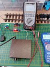
Quick example below with a Single Port Switch Decoder, requires configuring for using a Loco Address, operates ON and OFF by Function Key 1, a Bridge Rectifier is required, because if advertently or accidentally activating F2, there will be Polarity Swap to the Relay Input.

Relay ON 19.2 VAC.jpg
Relay activated and ON, AC Voltage circuit complete.
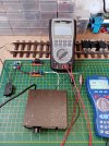
Relay OFF  0.0 VAC.jpg
Relay deactivated and OFF, AC Voltage circuit incomplete.

Use a Multimeter to verify Polarity Orientation from the Switch Decoder Output, before connecting the Relay, if self build Relay circuit DON'T forget to INCLUDE the diode!!!!!!!

Switch Decoder Output is in the region of 22 Volts, when the Relay Coil collapses, the regenerated voltage has to be dissipated, IF allowed to flow backwards the Switch Decoder is not long for this world!
 
Last edited:
I was wondering about getting an AC supply from the track for my water mill, but it is DCC and the frequency would be too high for the motor I believe.

I did toy with the idea of a building a low pass filter for 50 Hz, but never got around to making one and trying it out....
 
Ideal use for a half cooked decoder, where the motor drive has failed, but the Function outputs still work.

Some people have drawers full of bits like this!

Malcolm
 
Thanks for the replies. If I can play this back to make sure I’ve got it right -

  1. I shouldn’t connect my windmill motor directly to the switch decoder output as the “electrickerry” of the two are not directly compatible.
  2. I need a separate suitable power supply for my windmill motor
  3. I use the switch decoder output as the on/off switch for this separate supply - rather like the headlamp relay in my car - so I can activate it via my Navigator
I confess I don’t understand all the electronic terminology, but if I’ve got the basics right my son who was a stage lighting electrician for rock bands should be able to help with getting and installing the bits and bobs.
 
Incidentally if anyone is looking for suitable transformers, not just for the POLA Motor, ESR in my neck of the woods is worth a punt, plus they have a huge collection of components, often hard to find or obscure, came up trumps many times, just a satisfied punter.
 
Me again. The logistics of running a suitable power supply from the house to the site of the windmill are challenging. So I wondered 2 things -

1 could I use a solar panel to provide the required voltage for the motor?
2. is there some kind of gubbins that could convert my Massoth DCC track power to provide the necessary power for the motor

I think, based on the earlier responses to my question, the answer to 2 is probably yes but it would need to be custom-made.

Thanks again
1. Solar panel will be a DC supply, not AC.

2. I refer you to my previous post. it might be possible to build a low pass filter to get 50Hz AC from your DCC track, but I've not tried it....
 
Check out this thread from when I was trying to set up a Massoth switch decoder and relay to switch an isolated section of track from DCC to Programming so i can drive locos onto it and make CV edits. Relay with Massoth Switch decoder

You want the Massoth switch decoder to power/control the relay using a switch address from the NAV. You do use the continuous drive setting in the 4-channel switch decoder. In your case you want the 'closed' circuit of your relay to provide the A/C (when the switch decoder is 'on'), and the open circuit to provide nothing.
 
I think it would be worth finding out if the motor will run on DC. If it is classed as a 'universal' motor, it should run on DC, and will require a lower voltage than specified for AC. That would be the simplest way of sorting it.

Ralphmp Ralphmp do you have an adjustable DC power supply with a readout for volts and amps? (or multimeters)

However if it is a induction motor (no brushes) then it isn't going to run on DC.
It must be possible to generate 12-16VAC by means of a microcontroller and H-Bridge. Having a look up, SPWM may be able to do it, there is some code and an explanation here: Arduino SPWM sine inverter.

You may even be able to use something like this: SMA34 More Power to SMA20 Decoders with Tips and Additions which has a built in H-Bridge (SN754410) - I have used these to generate a DCC signal at 22V (750mA), so I'm sure they would be just fine at 12-16V 60mA. I am unsure if the SPWM code and Geoff's Decoder code would work together, however it would be great if they did (being able to control motor / lights from over DCC). If they don't, then you could use the PCB to take DCC track power and convert it to the 50Hz AC you may require.

In principle, using either of the above should work. You could then either run from track voltage (depending on what your track voltage actually is) or with the use of a 12V battery, you could likely do your solar panel idea.
 
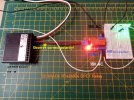
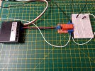
Took a bit of rummage to find the switch decoder, below is as simple as it gets!

Relay ON.jpg


Relay OFF.jpg


Look forward to seeing the working example of converting this.....

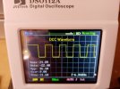
DCC Waveform.jpg
To this...............

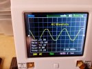
AC Waveform.jpg
 
The Shed - I agree that switching using your proposed method is simple using a switch decoder and a relay.

The difficult bit - turning a DCC waveform at 8-10Khz into a AC signal at 50Hz - I'm not sure I can see another way other than converting to DC and using something like a h-bridge to generate the AC.
 
Guys. Thanks for the info. I confess I don’t fully understand it all in detail, but I really do appreciate you taking the time to investigate.

I did wonder about trying to find a replacement motor but wasn’t sure what to get, so the eBay link is helpful.

Please bear with me whilst I read again all your helpful data and figure out what I need to do next.

Thanks again
 
Thinking outside the box a bit.
Likewise, seems somewhat odd that exchanging the AC motor for a DC one has not been considered before.

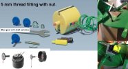
From the picture below, maybe at first glance not straightforward, perhaps with a Digital Caliper and ingenuity a solution could be found.

PS: Not me, have no need of either the Windmill or the Water Mill.

POLA 330090.jpg
 
Back
Top Bottom