You are using an out of date browser. It may not display this or other websites correctly.
You should upgrade or use an alternative browser.
You should upgrade or use an alternative browser.
Trainline Mallett an early Black one ref 2011002 not Zimo but had an onboard LGB plug in, now Batteryfied with LBG XlS
- Thread starter dunnyrail
- Start date
wandgrudd
Registered
Thanks Jon..
Is the magnet set-in-to / glued-on the collar of the gear?
I am used to the older models, where the magnet is a separate ring, you glue to the axle..
Thanks,
PhilP.
Phil i was thinking on the same lines but then noticed on the other pictures you can see the little magnets on the white gear.
Attachments
I wonder if indeed the sensor is trashed one of these would appear to fit the bill as a replacement:-

Hall Effect Magnetic Sensor Linear Switch Electric Car 49E SS49E S49E Z75 | eBay
Find many great new & used options and get the best deals for Hall Effect Magnetic Sensor Linear Switch Electric Car 49E SS49E S49E Z75 at the best online prices at eBay! Free delivery for many products!
www.ebay.co.uk
Phil i was thinking on the same lines but then noticed on the other pictures you can see the little magnets on the white gear.
Yes the 4 Magnets are on the Gear Boss.
Neil Robinson
Registered
Are you saying that there is no voltage between the +5V and GND wires in post 18's diagram?Set up to test the Hall Sensor as you suggested, no Voltage noted so I guess this must be the Problem. I wonder if an actual Touch of the Magnet could have trashed it?
D
Deleted member 4232
Guest
Moved
Last edited by a moderator:
Greg Elmassian
Guest
echoing Neil, if you don't have 5 volts between +5 and GND you have a more fundamental problem.
Solve that issue first... the sensor might be fine.
Greg
Solve that issue first... the sensor might be fine.
Greg

Greg Elmassian
Guest
went back and read... only saw him post that he tried a 5v supply.
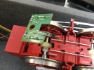
Looking at the picture, you can see what is connected to what:

so, this is what I see:
the right hand ends of the reeds and the middle leg of the sensor appear to be connected to GND
+5 goes to the near leg of the sensor
A is the output of the sensor (which normally goes low when triggered, sort of high when not)
P is reed 2 (open, goes to ground when triggered)
G is reed 1 (ditto)
The first thing is to be sure you get 5 volts between +5 and GND..
Next, you would want to watch the A output and see it go to ground PROVIDED it is connected to the decoder, otherwise it might not read what you think... there may be a "pull up" resistor on the decoder board...
Greg
Looking at the picture, you can see what is connected to what:
so, this is what I see:
the right hand ends of the reeds and the middle leg of the sensor appear to be connected to GND
+5 goes to the near leg of the sensor
A is the output of the sensor (which normally goes low when triggered, sort of high when not)
P is reed 2 (open, goes to ground when triggered)
G is reed 1 (ditto)
The first thing is to be sure you get 5 volts between +5 and GND..
Next, you would want to watch the A output and see it go to ground PROVIDED it is connected to the decoder, otherwise it might not read what you think... there may be a "pull up" resistor on the decoder board...
Greg
Ok so what I was trying to do was test it out by supplying 5v to the Hall Sensor with the board not connected to the Chip. Looks like I need to test it the other way round with the Chip Powered Up, or at least receiving power. Would not be possible I believe to have the Wheels Turning with the Bottom Wheel Securing Plate off. Though perhaps if I just powered up the Rear Bogie and left the front one unplugged except for the Circuit to the Hall Sensor that may allow me to prove that the Hall Sensor is getting power as it should, I could also test out that the Reeds are working as well.echoing Neil, if you don't have 5 volts between +5 and GND you have a more fundamental problem.
Solve that issue first... the sensor might be fine.
Greg
Correct Jon,
If the board is in 'free-air', you can test the reed outputs with any old magnet.. Same magnet waved past the Hall sensor, should give an output as well. - This will be a little more subtle, than the off/on of a reed, but you should still 'see' the output go to near ground.
If the board is in 'free-air', you can test the reed outputs with any old magnet.. Same magnet waved past the Hall sensor, should give an output as well. - This will be a little more subtle, than the off/on of a reed, but you should still 'see' the output go to near ground.
So tried that out and the result was a little inconclusive. Certainly the Hall Sensor Value as read by the Meter Changed by being a number to a much lesser one. As a last resort I have put all the Pickups back in Place and tried it out on Track Power. Still no Chuff.
Looking likely that the Chip is somehow or somewhere deranged or that the Hall Sensor is in some way faulty.
Looking likely that the Chip is somehow or somewhere deranged or that the Hall Sensor is in some way faulty.
So, to re-cap, you can control whistle etc. but no 'chuff'?
Do you get 'standing sounds'? - Coal shovelling etc.
Have you tried ALL the usual suspect keys to turn 'sound' on? F6, F8, F3, F4..
Do the sounds you get, tie-up with the function key designations in the instructions?
Have you checked the 'starting' CV values for sound?
Do you get 'standing sounds'? - Coal shovelling etc.
Have you tried ALL the usual suspect keys to turn 'sound' on? F6, F8, F3, F4..
Do the sounds you get, tie-up with the function key designations in the instructions?
Have you checked the 'starting' CV values for sound?
So, to re-cap, you can control whistle etc. but no 'chuff'?
...A yes
Do you get 'standing sounds'? - Coal shovelling etc.
...A yes
Have you tried ALL the usual suspect keys to turn 'sound' on? F6, F8, F3, F4..
...A yes the Sound comes on and off with F6. I showed that on my short vid Post 15.
Do the sounds you get, tie-up with the function key designations in the instructions?
...A yes
Have you checked the 'starting' CV values for sound?
...A no what CV is this please? Hm May be different between an XLS and this Chip as shown on this list, at Left is the XLS set.

Many thanks to all for your continuing assistance in trying to resolve this problem.
Last edited:
D
Deleted member 4232
Guest
Moved
Last edited by a moderator:
Greg Elmassian
Guest
I'd say if you saw a variation in the meter reading on the sensor output, the sensor is most likely good.
I'm with John S here look at configuration... since the sensor appears to work.
Greg
I'm with John S here look at configuration... since the sensor appears to work.
Greg
Have not responded to the last replies as there is an important Show on this weekend. But I must say many thanks to all those that have propelling this thread to last weeks Most Populat Topic. Who would have thought?
Thanks John S, did not reply earlier as you were clearly busy and I thank you for the Document. Sadly in German but interestingly some of the CV Values are a little different to my one.Jon, translated the original German document to English, can be found here,
HSB – Google Drive
drive.google.com
Split into two sections for downloading.
For reference to........
Page 6, Handbook HSB Mallet[10-23].de.en
- Speed encoder input activated (CV975 = 1)
Apologises for the editing, rush job, trying to get organised for the journey North.....
But we have some progress, well a little. Looking at CV 975 the Value in my Brochure and the Loco as read was 129. Changed it to 128 and lo and behold I am getting 1 just 1 Chuff per revolution! The English translation for CV 975 says ‘Clock External Inverce’ what ever means. So logic said that perhaps the 0..4 means number of beats per revolution. NO. 129 - 132 as values for CV 975 give no Chuff, only 128 Value gives that single Chuff.
So I delved into my XLS Brochure and CV’s 195-198 talk about Pulse Generatir and chuffs. However playing about with those CV’s gave no change so that was a dead end. These CV’s not in the TL Brochure.
Looking at things logically perhaps there is a Number of Beats CV to another CV with the CV 975, but have I reverted to some other way of creating a Chuff by loosing 1 from the Value? Curious.
Greg Elmassian
Guest
the cv "inverce" sould be "invert" or "inverse"... (although maybe that is how you spell inverse)
In any case it is related to the polarity of the signal from the sensor to the chip... leave it set so you get the 1 chuff per revolution, that means the "trigger logic" is proper.
There will be another CV for chuffs per revolution.
Greg
In any case it is related to the polarity of the signal from the sensor to the chip... leave it set so you get the 1 chuff per revolution, that means the "trigger logic" is proper.
There will be another CV for chuffs per revolution.
Greg
Similar threads
- Replies
- 5
- Views
- 4K
- Replies
- 0
- Views
- 1K
- Replies
- 8
- Views
- 3K