Track bus wiring for G scale

Andrew_au

Registered
12 Nov 2021
146
1
51
Sydney, Australia
Best answers
0
Country flag
Planning on putting in some wiring runs from my Control Centre to various tracks, including a run of about 10m.

Wire Size and Feeder Spacing suggests that for G scale I should be looking at 10-8 AWG wire (6-10 mm2). This feels very big to me. For comparison, power outlets in Australia typically use 2.5mm2 wire to carry 240 V / 15A. I know that the G scale wires are handling 8 kHz, but much less power (approx 24V / 6A).

The LGB standard power connector is twin wires at about 20 AWG (0.5mm2).

What is a sensible wire size for a 10m core run?
 

viaEstrecha

Spanish metre gauge in G scale (on the cheap)
25 Oct 2009
2,140
292
Bedfordshire
Country
United-Kingdom
Best answers
0
Country flag
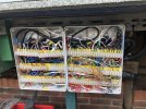
I rewired my railway last year and standardised on 1mm cross-section 16.5A 2 core (red/black) stranded copper thin wall flat automotive (24V) cable with black PVC outer, which I've found excellent outdoors over many years, with no degradation or power loss. I probably have 300m+ of the stuff out there for both track power and point motors and the cost of this wire was not prohibitive. I have put most of it inside flexible conduit, for neatness, and connect to the track a max of 5m apart. It just gets a bit busy where it all comes together!

IMG_3016 (Custom).jpgIronically, though it is all super reliable, I'm about to switch over to battery power!
 
Last edited:
8 Mar 2014
7,806
972
San Diego
Country
Armenia
www.elmassian.com
Best answers
0
Country flag
Andrew, you stated the key idea, but I think you did not grasp the way voltage and current compliment each other.

The reason your house runs at 240v instead of 24v is that for the same POWER, the 24v system would have to carry TEN TIMES the current.

So if you have a 100 watt light bulb, at 240v you only use (about) 0.41 amp (power is voltage times current)
at 24 volts, a 100 watt light bulb draws 4.2 amps...

So it should be clear that if your house was running 24 volts, your wires would carry TEN TIMES the current.

Therefore homes run at a high voltage, and have thinner wire.

Now there is another thing to consider, suppose your connections lose 10% of the voltage due to resistance (just as an example)

Well in your house your light bulb would get 216 volts, not great but it would work.
If your house (trains) lost 10% of 24 volts, then your light bulb or train would get 21.6 volts, and that would make a much larger difference to your 24v equipment.

Bottom line, when running at lower voltages you must be much more "on guard" of voltage drops and wire size, since smaller wire will have more voltage drop too.

Also, do not compare wire size based on LGB low current motors unless that is the only motor you run. Very few locos come with highly efficient motors, and you still must remember the voltage loss/drop of long wires and multiple connections that add resistance.

It all makes sense if you work out voltage losses from thin wire and resistance of connections.

Greg
 

Rhinochugger

Retired Oik
27 Oct 2009
36,772
4,243
North West Norfolk
Best answers
0
Country flag
Yep, I run DC, and have an underground cable that goes across the garden roughly bisecting the circuit.

I was advised to use 6mm2 cable (which over here is most commonly used domestically for wiring in cookers) and I don't get any noticeable voltage drop - and no, I haven't used a meter to check.

When I did something similar on my previous layout, many people scoffed, and somebody went as far as criticising me for being irresponsible in encouraging a potential future occupant of the house to connect his cooker in the garden :lipssealed::lipssealed:.

All I would say was that the advice I was given was based on an electrical engineer's calculations for voltage drop based on the voltage, current and distance that I had specified.
 

Andrew_au

Registered
12 Nov 2021
146
1
51
Sydney, Australia
Best answers
0
Country flag
It all makes sense if you work out voltage losses from thin wire and resistance of connections.
So lets take the radical next step of actually showing me how to do this to answer the question asked. So far, I've asked for a fish, and rather than giving me a fish or showing me how to fish, you've explained that eating and catching fish are different.

What is a sensible wire size for a 10m core run?
 
8 Mar 2014
7,806
972
San Diego
Country
Armenia
www.elmassian.com
Best answers
0
Country flag
Andrew, please bear with me. I'm a little taken aback at your response.

You often come on with a highly technical question, diving deep into the mechanics and or physics of the situation. Many times with what I might term "unusual takes" at physics or other sciences.

Now you are pissy with me to try to give you a foundation for why wire gauge is important, and not understanding why lower voltages need bigger wire. This is fundamental.

Even more out of character, instead of wanting the details of how and why, you just want the answer.

As the topper, you have not given enough information for me to give you an answer of any quality. (how many trains at once, measured current draw, track voltage, type of rail joiners, method of attaching wires to each other and the rails, etc.)

Greg
 
  • Like
Reactions: 1 user

Andrew_au

Registered
12 Nov 2021
146
1
51
Sydney, Australia
Best answers
0
Country flag
Greg,

Let me work through this in detail.
Andrew, you stated the key idea, but I think you did not grasp the way voltage and current compliment each other.
You start your answer by calling out a supposed personal failing of the questioner. Regardless of its accuracy, this puts a negative spin on everything that follows.

Now, obviously I don't understand something or I wouldn't be asking the question, but for the sake of charity assume that I'm radically simplifying the problem or a little unclear on terminology rather than generally ignorant.
The reason your house runs at 240v instead of 24v is that for the same POWER, the 24v system would have to carry TEN TIMES the current.

...

Bottom line, when running at lower voltages you must be much more "on guard" of voltage drops and wire size, since smaller wire will have more voltage drop too.
This is all well and good, but it's also all background. I know they are factors to consider, what I don't know is how to consider them.

It all makes sense if you work out voltage losses from thin wire and resistance of connections.
So after all that, you're about to tell me how to apply it to the problem at hand, right? Or at least give an example to justify whether the DCC Wiki values are sensible - which would allow me to compare my situation to theirs and make a judgement call?

Apparently not.

As the topper, you have not given enough information for me to give you an answer of any quality. (how many trains at once, measured current draw, track voltage, type of rail joiners, method of attaching wires to each other and the rails, etc.)
Yes, my question is missing information. But then, so is the DCC wiki article I referenced.

That said, there's more than enough information to provide some useful starting points.

Example: I specify 24v / 6A and 10m. And provided for comparison 2.5mm housing wire. Some suggested answers:
  • "If you run a DCC signal through 10m of 2.5mm wire, you will lose (?) volts (show calculation). In contrast, if you use 10m of (?), you will only lose (?) volts"
  • "I use wire (?) for my runs at home, which are (?)m long and carry 24v/(?)A. Loss is at most (?)v."

Pushing further:

viaEstrecha says that he uses 1mm cross-section auto wire, which if I've understood correctly will work out to about 0.78mm2 (0.5^2 * pi). This is substantially less than 6-10mm2.

In contrast, Rhinochugger does use 6mm2, which is consistent with the DDC wiki guidelines.

Meanwhile, I've been using a 5m run of LGB 51235 hook up wire (about 20 AWG) to run from the Command Station to my track, and then primarily using just the track to distribute DCC around ~82m of LGB track (longest distance from junction point about 10m). Joins are a mix of standard fishplates, fishplates with graphite paste, and Massoth rail joiners. Haven't had any problems obviously related to power distribution. Locos are 3x LGB from around 2000 - 2x 2-axle starter locos and a 28002 0-8-0 Rugen. I've been trying to get my hands on an RRAmpMeter IV but I haven't found an Australian distributor.


Even more out of character, instead of wanting the details of how and why, you just want the answer.
No, but I do want an answer I can work from.

Generally, every time I ask a question I'm asking two questions.
  • How do I apply this to a specific example that I'm thinking of? This might be something I'm currently doing or something I'm thinking about doing in the future.
  • How do I generalise this to a class of problems?
In this case, I have a problem where my programming and service area is inside the house but my layout is outside. At present, this means physically moving the command station around when I want to service / run trains. Command station is a z21 connected to my home wi-fi, so I don't need physical connection to the command station to run trains, but I need the connection to the track.

The inside location is close enough to the yard that I'm with a few metres of one extreme end of the layout, so I plan to leave the command station indoors and run a patch lead out to the railroad. However, I wanted a better run to somewhere in the middle (where most of the track and accessories are) rather than just to one end. Thus the 10m figure and trying to decide what quality of wire I need to run for the main bus. While I was at it, I was thinking about running some additional taps.

While trying to spec this all out, I realised that the 8-10 AWG wire suggested by the DCC Wiki is very big compared to most other household or electrical wire, and even bigger compared to the wire I was already running. I was more concerned about signal corruption than power loss, although am aware both are factors on long runs.

I also wanted things set up so I could replace the long run with a booster in the future, if appropriate.


Also looking for advice about feeder wire taps. Assuming a single supply point (and ignoring considerations of control / detection / reversing loops), is there value in dividing the track into insulated power sections, or is it OK to have (electrically speaking) entire loops of rail with multiple taps from the feeder bus? Is there a maximum / minimum number of taps for reliable operation?

Despite having 3 loops with sidings, the layout is currently just two "rails" with a single tap. While re-doing other wiring, I'm happy to restructure this as required.
 

phils2um

Phil S
11 Sep 2015
1,522
423
Ann Arbor, Michigan
Country
United-States
Best answers
0
Country flag
Hi Andrew,

Here is some helpful information and a website, Voltage Drop Calculator, that will figure out the voltage drop for you.

The following is an example of results from the Voltage Drop Calculator. For my situation which is a 70 ft one way run of 12 awg wire. I assumed a maximum current of 5 amps at 22 Volts AC which the limit of my boosters. This shows a maximum voltage drop of 1.22V or 5.55% which is something I can live with. By the way, I'm also losing about another 0.2V with the roughly 5 foot 1.5 mm^2 connecting wire between my boosters and the 12awg bus wire.

12awg, 70ft.png

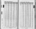
The tables below are from Thomas J Glover, Pocket Ref Fourth Edition, Sequoia Publishing, Inc. 2015. This is a very handy little volume with all sorts of helpful information and answers to just about any question - even those you never thought you had! I recommend everyone have a copy.

Copper wire resistance tables.jpeg

If you use the tables to calculate voltage drop for smaller gauge wire remember to double the length to get total resistance for your wire run - the current goes out and back!
 
8 Mar 2014
7,806
972
San Diego
Country
Armenia
www.elmassian.com
Best answers
0
Country flag
I wrote several replies. Erased them all.

When you are nicer and less confrontative, then I will help. This is supposed to be fun. This exchange is not. I don't need to pour my energy in to this mess when others appreciate help. If you know everything already, don't ask. If you don't know everything already, listen to the people who help you.

I tried to help and you crapped on me twice.

Out...
 

dunnyrail

DOGS, Garden Railways, Steam Trains, Jive Dancing,
Staff member
GSC Moderator
25 Oct 2009
26,206
4,997
75
St.Neots Cambridgeshire UK
Best answers
0
Country flag
I think we tend to overthink this wire thing.

Distance can be an issue and I have been rubbished on what worked well for me for getting on 15 years at my current and previous line using DCC Track Power. I used speaker hookup wire for all my sections. The line was split into discernible sections with a feed at each end of each section. The layout was based on power districts though they were just switchable track feed sections similar to Analogue but not so many, helped with odd power issues mostly related to Clamps not being tightened up. Though I did have a short once which turned out to be an Aristo set of screws below the track shorting out on my ally viaduct when a LGB 2-10-2 only passed over it!

The longest run from the Base Unit (with no booster) was 80 foot and I never had any noticeable issues of traction or sound confusion other than those created by dirty track. All wires run in Electritians cable conduit, the type that the top lifts off, makes it so easy for alterations. My pneumatic cable for Air Points also run through those conduits as well and still do as do some of the now unused wiring runs.
 

Andrew_au

Registered
12 Nov 2021
146
1
51
Sydney, Australia
Best answers
0
Country flag
Hi Andrew,

Here is some helpful information and a website, Voltage Drop Calculator, that will figure out the voltage drop for you.

The following is an example of results from the Voltage Drop Calculator. For my situation which is a 70 ft one way run of 12 awg wire. I assumed a maximum current of 5 amps at 22 Volts AC which the limit of my boosters. This shows a maximum voltage drop of 1.22V or 5.55% which is something I can live with. By the way, I'm also losing about another 0.2V with the roughly 5 foot 1.5 mm^2 connecting wire between my boosters and the 12awg bus wire.

View attachment 303585
Thanks Phil, that's very helpful. For some reason the page wigged out in Safari, but rendered fine in Chrome.

For 10m 24V/6A at 12 AWG I get a 0.63V drop. 0.39 at 10 AWG. 0.21 at 8 AWG. Obviously I'm normally running less than 6 A, but like you I used the limit of my command station (or booster) as a calibration. While these numbers are all "pretty small", it does seem like there's noticeable benefit in using "large" wire for as much of the run as possible.

My command station actually puts out just under 20V on the track outputs, so keeping the drop small will help.

Some follow-on questions:

The DCC Wiki makes a big deal about keeping the wire pairs in close contact with each other. This doesn't seem to factor into the calculator's analysis at all.

Are there particular advantages (assuming no breakages, etc) to having multiple feeders to G-scale track? If using multiple feeders, are there advantages to breaking the track up into power districts vs one continuous pair of rails?

Though I did have a short once which turned out to be an Aristo set of screws below the track shorting out on my ally viaduct when a LGB 2-10-2 only passed over it!
That is funny! Though it must have been very frustrating / confusing until you figured it out!
 

dunnyrail

DOGS, Garden Railways, Steam Trains, Jive Dancing,
Staff member
GSC Moderator
25 Oct 2009
26,206
4,997
75
St.Neots Cambridgeshire UK
Best answers
0
Country flag
Thanks Phil, that's very helpful. For some reason the page wigged out in Safari, but rendered fine in Chrome.

For 10m 24V/6A at 12 AWG I get a 0.63V drop. 0.39 at 10 AWG. 0.21 at 8 AWG. Obviously I'm normally running less than 6 A, but like you I used the limit of my command station (or booster) as a calibration. While these numbers are all "pretty small", it does seem like there's noticeable benefit in using "large" wire for as much of the run as possible.

My command station actually puts out just under 20V on the track outputs, so keeping the drop small will help.

Some follow-on questions:

Are there particular advantages (assuming no breakages, etc) to having multiple feeders to G-scale track? If using multiple feeders, are there advantages to breaking the track up into power districts vs one continuous pair of rails?
Well I think so as intimated in my reply above.

Power districts in general DCC terms are a different issue and usually have a different connected DCC power supply. This gives more power for heavy loads like a really large amount of locomotives on track and running.

But I call what are in effect track sections ‘power districts’ though as some would say it is wrong but entirely makes sense to me.
 

dunnyrail

DOGS, Garden Railways, Steam Trains, Jive Dancing,
Staff member
GSC Moderator
25 Oct 2009
26,206
4,997
75
St.Neots Cambridgeshire UK
Best answers
0
Country flag
Thanks Phil, that's very helpful. For some reason the page wigged out in Safari, but rendered fine in Chrome.

For 10m 24V/6A at 12 AWG I get a 0.63V drop. 0.39 at 10 AWG. 0.21 at 8 AWG. Obviously I'm normally running less than 6 A, but like you I used the limit of my command station (or booster) as a calibration. While these numbers are all "pretty small", it does seem like there's noticeable benefit in using "large" wire for as much of the run as possible.

My command station actually puts out just under 20V on the track outputs, so keeping the drop small will help.

Some follow-on questions:

The DCC Wiki makes a big deal about keeping the wire pairs in close contact with each other. This doesn't seem to factor into the calculator's analysis at all.

Are there particular advantages (assuming no breakages, etc) to having multiple feeders to G-scale track? If using multiple feeders, are there advantages to breaking the track up into power districts vs one continuous pair of rails?


That is funny! Though it must have been very frustrating / confusing until you figured it out!
Boy was it, but there was a fiz in close proximity to it and the loco worked ok elswhere.
 

Andrew_au

Registered
12 Nov 2021
146
1
51
Sydney, Australia
Best answers
0
Country flag
But I call what are in effect track sections ‘power districts’ though as some would say it is wrong but entirely makes sense to me.
Yep. There are a variety of reasons for deliberately partitioning track, including but not limited to occupancy detection, speed control sections, reversing loops, isolation, boosters, and limiting the scope of short circuits. Just trying to get a feel for whether there is significant benefit in partitioning if none of the above apply.
 

PhilP

G Scale, 7/8th's, Electronics
5 Jun 2013
33,592
3,525
Nottingham
Best answers
0
Country flag
If you have an obscure fault, then being able to isolate5different sections of your track is useful for fault-finding..

Theoretically, your two rails are a transmission line, and you feed at one end, with a termination at the other..
However, in practice, multiple feeds tend to increase resilience, and you do not tend to suffer from the multiple signal-paths causing interference.

PhilP
 

phils2um

Phil S
11 Sep 2015
1,522
423
Ann Arbor, Michigan
Country
United-States
Best answers
0
Country flag
Are there particular advantages (assuming no breakages, etc) to having multiple feeders to G-scale track? If using multiple feeders, are there advantages to breaking the track up into power districts vs one continuous pair of rails?
My opinion is that multiple feeds and individual power "districts" are essential. Although the rail we use is a great conductor, often better than the feeders, every rail joint is a major point of resistance unless solid mechanical joiners or soldered jumpers are employed. I've never been proficient at soldering wires to heavy sections such as rail without applying too much heat and melting stuff so I rely on Split-Jaw and Massoth type rail joiners. I also have a continuous power bus with drops about every 3 meters to feed the rails on most of my RR. Belt and suspenders for me!

Splitting the RR into separate power districts helps make trouble-shooting much easier and can shorten the length of the wires back to the command station/boosters.

The DCC Wiki makes a big deal about keeping the wire pairs in close contact with each other. This doesn't seem to factor into the calculator's analysis at all.
That is because the calculator assumes 60Hz sinusoidal current delivery. First, let me say I'm not an electrical engineer. It is my understanding that at this frequency and shape of current delivery twist is not a factor. But a square wave type current delivery, like that used to transmit DCC power and signal, actually has very high frequency components. That is how the signal rises and falls almost instantaneously. A pair of wires need to be in close proximity to effectively transmit the very high frequencies associated with square waves because of inductance in the wire. Whenever current flows through a wire a magnetic field is induced. Keeping a circuit's two wires in very close proximity (by twisting them together) causes the magnet fields around the wires to cancel out. Significant distortion of high frequency current happens without this magnetic field cancelation. The distortion manifests itself as "ringing" and rounding over of the sharp edges of the square wave. If the waveform is distorted enough, DCC decoders no longer recognize the encoded digital signal and interpret the waveform as just on and off DC. Perhaps an EE out there can confirm or deny.
 
Last edited:

DavidH

Registered
16 Sep 2017
18
11
Cumbria U.K.
Best answers
0
Country flag
My opinion is that multiple feeds and individual power "districts" are essential. Although the rail we use is a great conductor, often better than the feeders, every rail joint is a major point of resistance unless solid mechanical joiners or soldered jumpers are employed. I've never been proficient at soldering wires to heavy sections such as rail without applying too much heat and melting stuff so I rely on Split-Jaw and Massoth type rail joiners. I also have a continuous power bus with drops about every 3 meters to feed the rails on most of my RR. Belt and suspenders for me!

Splitting the RR into separate power districts helps make trouble-shooting much easier and can shorten the length of the wires back to the command station/boosters.


That is because the calculator assumes 60Hz sinusoidal current delivery. First, let me say I'm not an electrical engineer. It is my understanding that at this frequency and shape of current delivery twist is not a factor. But a square wave type current delivery, like that used to transmit DCC power and signal, actually has very high frequency components. That is how the signal rises and falls almost instantaneously. A pair of wires need to be in close proximity to effectively transmit the very high frequencies associated with square waves because of inductance in the wire. Whenever current flows through a wire a magnetic field is induced. Keeping a circuit's two wires in very close proximity (by twisting them together) causes the magnet fields around the wires to cancel out. Significant distortion of high frequency current happens without this magnetic field cancelation. The distortion manifests itself as "ringing" and rounding over of the sharp edges of the square wave. If the waveform is distorted enough, DCC decoders no longer recognize the encoded digital signal and interpret the waveform as just on and off DC. Perhaps an EE out there can confirm or deny.
Just getting into dcc, and interested in the power district concept. This seems essential for the smaller scales where power management and overload protection is recommended. How would you recommend wiring the power districts for G scale? I see digitrax make a 4 way power management module PM42. Do Massoth have something similar. Help appreciated as it sounds like getting all this planned correctly at the outset is a must.
Thanks
David
 

dunnyrail

DOGS, Garden Railways, Steam Trains, Jive Dancing,
Staff member
GSC Moderator
25 Oct 2009
26,206
4,997
75
St.Neots Cambridgeshire UK
Best answers
0
Country flag
Do you intend to have multiple lashups of high power hungry USA type diesels? If not then power districts in terms of providing extra power districts (more inputs and added dcc power supplies) for allowing that power to be used are not for you. My post #12 and others explains the benefits of splitting your line into sections.

But as always, what do you want or are planning to do? The answer to this i.e. what is your specification before a solution can be explained?

If you do track sections you can always use them to add additional District Power should you need to do so in the future if your needs expand. Oh so you know Massoth do a “DiMax Booster” which gives your system an additional 12Amps of power if you need it. Cost currently £530.


Dan

Registered
28 Jan 2010
660
52
Eastern MA, USA
Best answers
0
Country flag
While this discussion is about wires and power drops, one must remember that the track with good rail clamps {I use train-li}(no joiners!!) will also carry the power. I use this to wire my layout and use #14 outdoor low voltage wiring 2 pairs of wires (USA) to the LGB 90 degree crossover. My loop/s are a figure 8 thus power flows in all directions of the rails from the crossover. If a section has a power loss then there are 2 bad connections and I find a pair once every 4 or 5 years. I am in southeastern Massachusetts and weather varies from -10 F to 100 F and I get lots of snow/ice and high humidity in the summer. I mention all of this as where you live can determine how you need to keep track powered long term and depends on where you live.
 
8 Mar 2014
7,806
972
San Diego
Country
Armenia
www.elmassian.com
Best answers
0
Country flag
As the topper, you have not given enough information for me to give you an answer of any quality. (how many trains at once, measured current draw, track voltage, type of rail joiners, method of attaching wires to each other and the rails, etc.)
Yes, my question is missing information. But then, so is the DCC wiki article I referenced. (what kind of response is that?)

From Greg:
Still no info on how many trains at once, current needed, track voltage goal, types of rail joiners, how you are attaching wires.

unbelievable....