Very nice lots of potential for Timetable Operating. When the first post about the Willow came up I was going to mention it. Had one in my last Garden, but a baby compared to yours. Got so fed up of the Leaves on the Line that one day the Chain Saw came out. No more Willow, never regretted it except for the nice cooling effect on a very hot day when sat beneath it. But those leaves, seamed to be falling off the thing all year. It did make Running the line a bit of a trial having to clear them before every running session. Truth be told I bet you do not miss your one now that it has gone.
You are using an out of date browser. It may not display this or other websites correctly.
You should upgrade or use an alternative browser.
You should upgrade or use an alternative browser.
The AGC
- Thread starter adverse camber
- Start date
Madman
Registered
After some years enjoying watching other peoples' pictures of them building their railways, I thought I would share some of mine now that I have finally (hopefully) managed to work out how to batch downsize the images.
The AGC (Atchison, Girdlestone and Creed) Railroad started life when we moved in 2010. There were two previous (smaller) railroads before that so I had some idea of what I was setting out to achieve.
I will try and tell the story as we go along.
We are fortunate to have a large (>1 acre) garden, and part of the deal for moving (like most men I was a little reluctant to be uprooted)_ was that a section of it, fortunately nicely hidden away from most of the rest of the garden was mine for trains.
The first thing was to clear the area, and then put up a shed to get all the boxes out of the roof!View attachment 248182View attachment 248183View attachment 248184View attachment 248185View attachment 248187
If I can make this post work I will continue with the story!
That's a shed ? I've seen living rooms that don't look that good. Chandeliers, cathedral ceiling, wow ! If your shed looks like it does, I imagine your railway should be stunning.....

Well I posted this before continuing along your thread. Truly a magnificent railway !
Last edited:
railwayman198
Registered
This is very impressive and it must be really satisfying to see it develop. I'm also admiring the lovely old flint? wall that makes such an attractive backdrop to the layout. I too have a few box trees. Those in the front garden have already been attacked by box moth caterpillars but those on the layout in the back garden are unaffected so far.
adverse camber
Registered
With retirement looming and no weeping willow it was time for a little creative expansion.
This was much aided by attending a local auction at which the remains of a huge LGB layout in a now defunct shop were being disposed of. Prices at these auctions have gone up with the advent of bidders on line but that only works if you can put the item in the post. Does not apply to huge boxes of used flexible LGB track.. I only bought two of the 6 available, but they weighed about 40 kg each and I ended up with about 70-80meters of track for £250. The stuff us garden railroaders have dreams about.
OK some of it was pre-bent but could be straitened, and some of the rails had gouges where I suspect the track cleaner had stalled with it abrasive wheels running. Something I recognise from my own experience. But most of it was fine if a bit grubby. This combined with the space left by the willow tree was an opportunity not to pass up.
The plan

this was the existing area with all the buildings tucked up for the winter
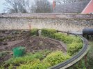
The paving slabs on the left had settled over time and needed to be lifted about 3cm. The tree had been in the green area left center with the low hedge and track round it

the tree stump is just visible as the dark blob in the centre half hidden by the hedge

the biggest problem was the drop of about 55cm from the track level down to the tree stump level. this was down this slope which does not show very well but the sleepers give you some idea of the drop involved. I wanted to keep the gradient down to a maximum of 1:25. Happy for it to be steeper than the main line as I envisage this as a branch logging line with tighter curves and gradients, running shorter trains.

another view of the slope down which trains had to run.

and from a different angle with the stump obvious now

for materials I had 2 rockeries elsewhere on the line which I was going to take apart and this pile of stone I picked up some years before in a car boot sale. Also visible are the upturned ends of some cast concrete bridges I made for my very first railway but have not used since. They are very heavy and have now moved house twice!

this rockery is a pile of broken stone slabs with some bigger bits
This was much aided by attending a local auction at which the remains of a huge LGB layout in a now defunct shop were being disposed of. Prices at these auctions have gone up with the advent of bidders on line but that only works if you can put the item in the post. Does not apply to huge boxes of used flexible LGB track.. I only bought two of the 6 available, but they weighed about 40 kg each and I ended up with about 70-80meters of track for £250. The stuff us garden railroaders have dreams about.
OK some of it was pre-bent but could be straitened, and some of the rails had gouges where I suspect the track cleaner had stalled with it abrasive wheels running. Something I recognise from my own experience. But most of it was fine if a bit grubby. This combined with the space left by the willow tree was an opportunity not to pass up.
The plan
this was the existing area with all the buildings tucked up for the winter
The paving slabs on the left had settled over time and needed to be lifted about 3cm. The tree had been in the green area left center with the low hedge and track round it
the tree stump is just visible as the dark blob in the centre half hidden by the hedge
the biggest problem was the drop of about 55cm from the track level down to the tree stump level. this was down this slope which does not show very well but the sleepers give you some idea of the drop involved. I wanted to keep the gradient down to a maximum of 1:25. Happy for it to be steeper than the main line as I envisage this as a branch logging line with tighter curves and gradients, running shorter trains.
another view of the slope down which trains had to run.
and from a different angle with the stump obvious now
for materials I had 2 rockeries elsewhere on the line which I was going to take apart and this pile of stone I picked up some years before in a car boot sale. Also visible are the upturned ends of some cast concrete bridges I made for my very first railway but have not used since. They are very heavy and have now moved house twice!
this rockery is a pile of broken stone slabs with some bigger bits
adverse camber
Registered
Work commences with plant clearance, most of these were moved to a vacant area of flowerbed hastily created away from the trains. and as always the biggest challenge is bot creating a track plan that allows for realistic operations and then actually making it fit in the space, particularly where there are points which always seem to me to be very inflexible just when you want to fudge things a bit.
sorting put the access from the main line and into the sidings on the left which were going to be extended.

the track roughed out. I was using some old R2 curves to set a minimum radius, though the final track would be flexi. with a drop of 50 cm I was going to need to travel about 13m to maintain the 1:25 gradient by the time I got to the bottom of the slope, where I was originally planning to simply join a double circuit round the tree stump area on the level...…..but it did not quite workout like that.

Once again out comes the laser, and in go the grading stakes

and then lots of digging. You can see the pile of spoil on the right of the picture.
I then realised that I had to get the top sidings and main line sorted to ensure that I started the down slope at the right point. It would also provide some stone from a dismantled rockery (not illustrated). so all the paving slabs had to be lifted, nd replaced slightly moved and 3cm higher. They are 2x2ft and very heavy. backache time

Slabs are just laid on impacted soil. It makes later lifting and movement much easier
Fortunately I had a few spare as I was extending the paved are a bit.
old ballast had to be moved and the area of half slabs made longer to accommodate the new extended sidings
The paving has been laid deeper beyond this into the area where the rockery (removed) used to be. This will accommodate a bigger town scape and possibly a fun fair


most of the slabs now laid, it was possible to sort out the level of the sidings and thus the gradients.
Removal of the rockey also provided the "mountain" round which the first descending curve would run.

Having carefully dug away all the soil to create the curve in the foreground I began, much too late to think about how this line would join the envisaged double circuit at the bottom of the slope and how this might work operationally.
If it joined the outer circuit it would have to move to the inner one to reach any sidings, and if there was a simple crossover then it would be impossible to have a train running round the outer circuit all the time without there being inevitable crashes.
No the line down the hill needed to join the inner circuit and run into the sidings while a train could be set running round the outer one without needing to be under direct control all the time. This meant that the descending line would have to cross over the top of the circuits at the bottom before joining them, and that meant a bridge. I was also beginning to think about access. All track and beds makes this difficult. Back to the drawing board.
You know it is sometimes best to have thought all this through before you start. I had only been working on this idea for about 4 years.
sorting put the access from the main line and into the sidings on the left which were going to be extended.
the track roughed out. I was using some old R2 curves to set a minimum radius, though the final track would be flexi. with a drop of 50 cm I was going to need to travel about 13m to maintain the 1:25 gradient by the time I got to the bottom of the slope, where I was originally planning to simply join a double circuit round the tree stump area on the level...…..but it did not quite workout like that.
Once again out comes the laser, and in go the grading stakes
and then lots of digging. You can see the pile of spoil on the right of the picture.
I then realised that I had to get the top sidings and main line sorted to ensure that I started the down slope at the right point. It would also provide some stone from a dismantled rockery (not illustrated). so all the paving slabs had to be lifted, nd replaced slightly moved and 3cm higher. They are 2x2ft and very heavy. backache time
Slabs are just laid on impacted soil. It makes later lifting and movement much easier
Fortunately I had a few spare as I was extending the paved are a bit.
old ballast had to be moved and the area of half slabs made longer to accommodate the new extended sidings
The paving has been laid deeper beyond this into the area where the rockery (removed) used to be. This will accommodate a bigger town scape and possibly a fun fair
most of the slabs now laid, it was possible to sort out the level of the sidings and thus the gradients.
Removal of the rockey also provided the "mountain" round which the first descending curve would run.
Having carefully dug away all the soil to create the curve in the foreground I began, much too late to think about how this line would join the envisaged double circuit at the bottom of the slope and how this might work operationally.
If it joined the outer circuit it would have to move to the inner one to reach any sidings, and if there was a simple crossover then it would be impossible to have a train running round the outer circuit all the time without there being inevitable crashes.
No the line down the hill needed to join the inner circuit and run into the sidings while a train could be set running round the outer one without needing to be under direct control all the time. This meant that the descending line would have to cross over the top of the circuits at the bottom before joining them, and that meant a bridge. I was also beginning to think about access. All track and beds makes this difficult. Back to the drawing board.
You know it is sometimes best to have thought all this through before you start. I had only been working on this idea for about 4 years.
adverse camber
Registered
About the wall.
we live in a house built in the 1960's by my wife's grandfather. It was built in the garden of a much bigger house (now our next door neighbour) which was lived in by her family since 1920.
A significant part of the bit of the garden that her grandparents took to build the house was the old walled kitchen garden of the bigger house. Many kitchen gardens have high walls round them and much of our boundary is formed by a brick and flint wall. In our part of the UK flint was a common building material hence the brick and flint wall. It is at least 200 years old and may well be much older as we live in a village with many old buildings one of which features in the doomsday book!
adverse camber
Registered
back to the drawing board to see if it could be done, and out came the trust laser and the sticks to check the gradients
.JPG")
the line of steaks on the left are the circuit round the old willow stump, the line skiting the soil heap are the descending branch line from the main. I decided with a bit of gradient fiddle it could be done, sill leaving enough clearance for the bridge. I reckon you need 30 cm to be safe (including the bridge deck) but can squeeze in a bit less
.JPG")
at the same time to encourage myself and get a better idea of the slop I started ballasting the top siding area and putting it back on the main line
.JPG")
and finished building up the rockery area. I then covered it in soil in the hope the rain would wash it into all the cracks, in the end it did rain a bit but less than you would expect in winter and I had to do a lot of work with a stick and trowel to make this happen
.JPG")
.JPG")
Using the larger stones as a retaining wall I built the next layer down the slope and the edge of the lower circuit (partly obscured by the green tub). I decided to create a dry stream bed which I could use for access and to give some reason for the track to level off and because I had the bridge from a previous layout. the bridge on the left is the one crossing the lower circuit where you can just see the tops of the stones that create the deep cutting it runs though.
.JPG")
better view of the bridges and cutting
.JPG")
To make sure I was getting reasonable gradients, now ballasted down to the second bridge and work has started on the bottom section of the branch line connecting to the bottom circuit, now being done from inside the loop rather than outside it as originally planned. This section is going to be a bit steeper than planned but with a shay and short train it should cope OK (I hope)

there was still a big heap of soil in the center where the sidings where going to go

By far the most complex bit of track laying was going to be where the inner circuit and the descending branch line met at an R3 point and almost immediately beyond it there would be another point to the sidings.
I felt that there was no point in having two complete circuits. the track passing under the bridge could be single which meant I could use the bridge I already had, movement on the inner circuit would be from up and down the branch line, a reverse loop to turn the locos and enough room to act as a head shunt when needed. All this could be done while allowing continuous running on the outer line. The only down side would not be being able to run two trains in opposite directions on the circuits but that would not be very prototypical on the average logging line anyway!
Time to complete the branch line run to the bottom of the slope reduce the soil pile (lots of wheel barrow loads to another part of the garden, you can never have too much topsoil) and begin to stake out the sidings having sorted the point geometry
After consideration I found that a large bit of rock fitted quite nicely into the corner between the bridge and down ramp I had created so made a further small rockery here. You can see this just to the left of the spade stuck in the soil.
I also started putting the retaining wall (broken paving on edge) to make the circuit. This whole area was leveled off several years before by a sleeper retaining wall which you just see in places. This formed the outer retaining wall of the bottom circuit for 3/4 of its circumference.
the line of steaks on the left are the circuit round the old willow stump, the line skiting the soil heap are the descending branch line from the main. I decided with a bit of gradient fiddle it could be done, sill leaving enough clearance for the bridge. I reckon you need 30 cm to be safe (including the bridge deck) but can squeeze in a bit less
at the same time to encourage myself and get a better idea of the slop I started ballasting the top siding area and putting it back on the main line
and finished building up the rockery area. I then covered it in soil in the hope the rain would wash it into all the cracks, in the end it did rain a bit but less than you would expect in winter and I had to do a lot of work with a stick and trowel to make this happen
Using the larger stones as a retaining wall I built the next layer down the slope and the edge of the lower circuit (partly obscured by the green tub). I decided to create a dry stream bed which I could use for access and to give some reason for the track to level off and because I had the bridge from a previous layout. the bridge on the left is the one crossing the lower circuit where you can just see the tops of the stones that create the deep cutting it runs though.
better view of the bridges and cutting
To make sure I was getting reasonable gradients, now ballasted down to the second bridge and work has started on the bottom section of the branch line connecting to the bottom circuit, now being done from inside the loop rather than outside it as originally planned. This section is going to be a bit steeper than planned but with a shay and short train it should cope OK (I hope)
there was still a big heap of soil in the center where the sidings where going to go
By far the most complex bit of track laying was going to be where the inner circuit and the descending branch line met at an R3 point and almost immediately beyond it there would be another point to the sidings.
I felt that there was no point in having two complete circuits. the track passing under the bridge could be single which meant I could use the bridge I already had, movement on the inner circuit would be from up and down the branch line, a reverse loop to turn the locos and enough room to act as a head shunt when needed. All this could be done while allowing continuous running on the outer line. The only down side would not be being able to run two trains in opposite directions on the circuits but that would not be very prototypical on the average logging line anyway!
Time to complete the branch line run to the bottom of the slope reduce the soil pile (lots of wheel barrow loads to another part of the garden, you can never have too much topsoil) and begin to stake out the sidings having sorted the point geometry
After consideration I found that a large bit of rock fitted quite nicely into the corner between the bridge and down ramp I had created so made a further small rockery here. You can see this just to the left of the spade stuck in the soil.
I also started putting the retaining wall (broken paving on edge) to make the circuit. This whole area was leveled off several years before by a sleeper retaining wall which you just see in places. This formed the outer retaining wall of the bottom circuit for 3/4 of its circumference.
Attachments
adverse camber
Registered
The next ecit,ment was finding a whole lot of small garden trees cheap in local garden center. Not a great time to put them in but at about a pound each it was worth a punt. I am a gardener of the try it and see variety. For a project like this you need a lot of plants and since this is supposed to be a logging line that means trees. I put in about 40 of different types clumped according to species
you can see them between the tracks as it winds down the hillside

Hopefully these will get a lot bigger in the next couple of years. I know from experience that the fir trees (Xmas trees) though miniature can get very big so they are still in pots to limit their growth a bit.

another view of the trees

and then time to add further ballast. To get the track geometry absolutely correct as the bottom of the slope it was going to be necessary to lay the track on both the branch connecting line and the circuit lines s the tolerances for the points were going to be tight

roughing out the position of the points to both the branch line and the sidings

and finally track laying begins, starting at the top with the three sidings and their connection with the main line
In time I may replace the middle track point with a triple one to allow a run round from both inner and outer tracks, but I would have to buy one. It will be easy to replace if operating experience shows that that would be useful

Now track can start snaking down the slope. This is all flexitrack from my auction bargain bundle. I invested in a rail bender years ago. It only bends one rail at a time which means dissembling and assembling track, but the double rail versions cost arm and a leg.

Track now reaches all the way to the bottom and has linked up with the inner circuit.

While her you can see where the there is the single section of track on the bottom circuit where it runs under the bridge. The rest will be double.
Need to sort out the exact position of the inner part as it has to have a point off it not only for the sidings but also the turning Y so it is a case of lay a short section of ballast and track, sort the geometry, put in the retaining stones (for the ballast) and lay a bit more. if you try and do all the stones and then the ballast and then the track (as you can for a long strait run with no linkages) you end up making mistakes and having to move it all.
All the critical point now in place on the inner circuit. You can just make out the ones for the turning Y on the far left next to the hammer. The exact position of the sidings has still to be resolved
you can see them between the tracks as it winds down the hillside
Hopefully these will get a lot bigger in the next couple of years. I know from experience that the fir trees (Xmas trees) though miniature can get very big so they are still in pots to limit their growth a bit.
another view of the trees
and then time to add further ballast. To get the track geometry absolutely correct as the bottom of the slope it was going to be necessary to lay the track on both the branch connecting line and the circuit lines s the tolerances for the points were going to be tight
roughing out the position of the points to both the branch line and the sidings
and finally track laying begins, starting at the top with the three sidings and their connection with the main line
In time I may replace the middle track point with a triple one to allow a run round from both inner and outer tracks, but I would have to buy one. It will be easy to replace if operating experience shows that that would be useful
Now track can start snaking down the slope. This is all flexitrack from my auction bargain bundle. I invested in a rail bender years ago. It only bends one rail at a time which means dissembling and assembling track, but the double rail versions cost arm and a leg.
Track now reaches all the way to the bottom and has linked up with the inner circuit.
While her you can see where the there is the single section of track on the bottom circuit where it runs under the bridge. The rest will be double.
Need to sort out the exact position of the inner part as it has to have a point off it not only for the sidings but also the turning Y so it is a case of lay a short section of ballast and track, sort the geometry, put in the retaining stones (for the ballast) and lay a bit more. if you try and do all the stones and then the ballast and then the track (as you can for a long strait run with no linkages) you end up making mistakes and having to move it all.
All the critical point now in place on the inner circuit. You can just make out the ones for the turning Y on the far left next to the hammer. The exact position of the sidings has still to be resolved
mrcheddar
American Railroads, Swiss Railways, Travel
Very nice! I also use 1 to 1 scale sleepers for retaining walls. Those thing are heavy!
I like your long straight sections and wide bends. I have one of those Pola coaling towers. Apparently there where only about 2000 made?
I also have two Playmobile engines for visiting children. They don't want to go home once they get their hands on them.
I like your long straight sections and wide bends. I have one of those Pola coaling towers. Apparently there where only about 2000 made?
I also have two Playmobile engines for visiting children. They don't want to go home once they get their hands on them.
adverse camber
Registered
The body has been fine apart from a bit of back ache when moving all the heaviest rocks and paving slabs. Knee pads fitted into pockets in the front of my working trousers have been a great find. This sort of thing keep me fit.
I am surprised there were only 2000 coaling towers made. I have seen them on eBay from time to time and mine did not come with any suggestion of this when I bocught the kit. I know pola sometimes made a model and then produced it in a special limited edition with minor modifications. My pola turntable is one such, and I know they did this with a fancy motorised version of both the water mill and the sawmill kit.
I agree that playmobile for the young is fantastic. That and Lego were great favourites with my kids and my little granddaughter is already demonstrating that she is a chip off the old block. I have chipped up three old playmobile locos so they can run on DCC and have. A couple of radio controlled battery ones too. Only problem is the batteries don’t last long on such a long circuit and don’t do well on significant gradients.
Even if the wagons do get torn apart you can just snap them back together again
Thomas Lambo
RC, wood craftsmanship & culinary arts
Wonderful layout, and amazing story over several years of evolution.
I love these type of long term projects (slow and sure). I'm doing the same thing with my GR build, now two years into construction.
Once again, splendid work and thanks for taking the time to share with us")
I love these type of long term projects (slow and sure). I'm doing the same thing with my GR build, now two years into construction.
Once again, splendid work and thanks for taking the time to share with us
adverse camber
Registered
just had to finish shorting out the area at the bottom of the slope. This went pretty quickly though as you can see from the photos, some days were on the chilly side and tracklaying in subzero temperatures is not good as the track the ballast and my fingers all go solid.

Most of the track now laid. You can see the weed membrane sticking up round all the broken paving that retains the ballast. in the centeral area

Still have to complete the two circuits and the turning Y, which is inevitably given the geometry going to have some fairly tight radius track.

A couple of wet and cold weeks later and it is all done. The sidings are in, all the paving for the buildings has been laid, though these will not go out till it gets warmer, saw mill on the right, and a small town and station in the centre and on the left. Need to give the beds some thought, some will be trees but they will also need some ground cover. A friend want and Indian encampment which I think wounds like a good idea, just need to find the tee pees and Indians.

At last a decent image of the points arrangement at the bottom of the branch line. It is intended that all the shunting and manoeuvring can be done n the inner circuit leaving the outer free for something to round to keep things moving.
I am one of those people ho gets very cross when I see a big layout at an exhibitions with nothing happening on it. I firmly believe that visitors come to see trains moving about as well as admire the scenery.
You can just make out the last bit of track coming down the slope has a severe adverse camber on it. I have refashioned it once already. Logically making the inner rail tighter and very slightly shorter should sort the issue out but it does not seem to have done so. Any suggestions for sorting this problem gratefully received as it happens from time to time when track laying

This shows the completed turning Y.
Now all that is needed is the return loop box and to wire it. Unfortunately although I have 2 boxes they are both in use at the moment and wont become free till I have completed my next project. I am far too stingy to buy one just to fill in the few month gap, so no use of the Y for now.

looking up the side of the layout that runs parallel to the wall. This picture shows just how much gradient there is in the garden
On the left the area where the saw mill used to go being converted to a brewery

More details of the Brewery area, siding now in place and track back down on the main line. You can see a few piles of cut up thermalite blocks around the layout. These are cut to just fit inside the larger buildings. I had problems with these being blown over and damaged, all completely cured by placing them over the blocks that then prevent them from toppling.
And the same area seen from the other direction.
Now all that is needed is the rewiring and some test runs but that will have to wait for the weather to warm up a bit. I have also got a few models to make, just taken delivery of a Ferris wheel for the fun fair area looks like about 400 parts so that will take a while to put together.
Most of the track now laid. You can see the weed membrane sticking up round all the broken paving that retains the ballast. in the centeral area
Still have to complete the two circuits and the turning Y, which is inevitably given the geometry going to have some fairly tight radius track.
A couple of wet and cold weeks later and it is all done. The sidings are in, all the paving for the buildings has been laid, though these will not go out till it gets warmer, saw mill on the right, and a small town and station in the centre and on the left. Need to give the beds some thought, some will be trees but they will also need some ground cover. A friend want and Indian encampment which I think wounds like a good idea, just need to find the tee pees and Indians.
At last a decent image of the points arrangement at the bottom of the branch line. It is intended that all the shunting and manoeuvring can be done n the inner circuit leaving the outer free for something to round to keep things moving.
I am one of those people ho gets very cross when I see a big layout at an exhibitions with nothing happening on it. I firmly believe that visitors come to see trains moving about as well as admire the scenery.
You can just make out the last bit of track coming down the slope has a severe adverse camber on it. I have refashioned it once already. Logically making the inner rail tighter and very slightly shorter should sort the issue out but it does not seem to have done so. Any suggestions for sorting this problem gratefully received as it happens from time to time when track laying
This shows the completed turning Y.
Now all that is needed is the return loop box and to wire it. Unfortunately although I have 2 boxes they are both in use at the moment and wont become free till I have completed my next project. I am far too stingy to buy one just to fill in the few month gap, so no use of the Y for now.
looking up the side of the layout that runs parallel to the wall. This picture shows just how much gradient there is in the garden
On the left the area where the saw mill used to go being converted to a brewery
More details of the Brewery area, siding now in place and track back down on the main line. You can see a few piles of cut up thermalite blocks around the layout. These are cut to just fit inside the larger buildings. I had problems with these being blown over and damaged, all completely cured by placing them over the blocks that then prevent them from toppling.
And the same area seen from the other direction.
Now all that is needed is the rewiring and some test runs but that will have to wait for the weather to warm up a bit. I have also got a few models to make, just taken delivery of a Ferris wheel for the fun fair area looks like about 400 parts so that will take a while to put together.
Riograndad
Model Railroading, boats and oil painting,
Great build all round,if I only had more space and a flat garden to work with
korm kormsen
Registered
that is most impressive.
Very nice build, looks like you have been motivated to work through the Winter just like I was when I started thencurtent Dunnybahn. For Cold Days I was wearing a Lidl Thermal WorkSuit kept me well warm on the coldest days in 2013/14. But unlike you I had a neat all wet Spring 2013 to contend with which put back work no end. Still I persevered as I could. Noting that you are short of Boxes, I still have 2 on my For Sale Pages if they are of any use.View attachment 248598
This shows the completed turning Y.
Now all that is needed is the return loop box and to wire it. Unfortunately although I have 2 boxes they are both in use at the moment and wont become free till I have completed my next project. I am far too stingy to buy one just to fill in the few month gap, so no use of the Y for now.
LGB Track very short LGB 10040 Piece andSwitch Boxes still available UPDATE AGAIN - G Scale Central
Similar threads
- Replies
- 10
- Views
- 510
- Replies
- 8
- Views
- 247
- Replies
- 29
- Views
- 935
- Replies
- 4
- Views
- 339