Signal detection with both battery and overhead-powered equipment

JACOB551551

Registered
Hi all
Trying to figure out how to create automated signals for my garden railway that I'm planning.
For context, I'm planning on doing it on hard mode and have all my electric locos pull power from Alnolge OHLE (AC/DC, somewhere around 15 to 18V, not decided) and then use a DCC radio receiver for digital control. Steam and Diesel locos (if i get any) will be battery powered.

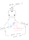
My current idea is to have the wheels on cars and locos shortened together with a switch, and have them complete a block relay circuit powered by a battery (or power supply). and only one of the running rails as a return for the OH circuit.

In your all's opinion, would this work? What are the concerns with this kind of setup?

I know I'm crazy for doing this.

An image to try and help explain my idea.
1758728467498.png
 
If you are going to be using DCC anyway, put it on the OHLE / Track..

There are methods of detecting where a train is, on DCC, so why comicate it further?

PhilP.
 
If you are going to be using DCC anyway, put it on the OHLE / Track..

There are methods of detecting where a train is, on DCC, so why comicate it further?

PhilP.
The main problem with DCC on OHLE, i would think, is signal integrity.

"So why complicate it further?" Because I want to try and do this kind of stuff.
im not asking for judgment on my "whys," im asking for judgment on my "how's"


Also not really looking to get into transponding or automation beyond automating signal aspects
 
Last edited:
Tis not recommended to use overhead with track current as common return. There are good reasons for this as much to do about possible crossovers of power on points as well as potential reverse loops. If you want automatic operation of signals keep conventional @ rail eithe DC or AC (DCC?) and use LGB EPL contacts and setup for this. Others would suggest computer DCC recognition or even micro switches with wheele activating the lever for location recognition.
 
Tis not recommended to use overhead with track current as common return. There are good reasons for this as much to do about possible crossovers of power on points as well as potential reverse loops. If you want automatic operation of signals keep conventional @ rail eithe DC or AC (DCC?) and use LGB EPL contacts and setup for this. Others would suggest computer DCC recognition or even micro switches with wheele activating the lever for location recognition.
The overhead will always be (+) and both running rails will be (-) with respect to "power voltage" (or the inverse). No data will be transmitted through the rails.
So the reverse loop concern is non-existent

No transponding of any kind is planned. i am only looking for (I/0) style occupancy detection that will work with any axle that is "shorted"

The goal of this is so the signal aspects will change relative to where i have my trains and how i have the points/switches set. I will always be in control of the locos and the switches.
 
The main problem with DCC on OHLE, i would think, is signal integrity.

A keep-alive capacitor is the way around that. The Southern California traction club runs its H0 scale traction layout from overhead power with DCC control and keep-alive boards in their streetcars and interurbans.

As far as reverse loops go, you would need to ensure that there is signalling section which is completely isolated from the adjoining rails within the loop, otherwise you may get false occupancy detection.
 
A keep-alive capacitor is the way around that. The Southern California traction club runs its H0 scale traction layout from overhead power with DCC control and keep-alive boards in their streetcars and interurbans.

As far as reverse loops go, you would need to ensure that there is a signalling section that is completely isolated from the adjoining rails within the loop; otherwise, you may get false occupancy detection.
Keep-alive capacitors do nothing for signal integrity, i use them all the time with my HO stuff. When a loco is relying on the cap, you have no control until it regains signal on good track.

Why do you think i wouldn't have multiple blocks?
 
In smaller scales they use resistive axles, an axle on each item of rolling stock as a resister soldered across to ensure a small current flow that is then measured via the block detectors.

The block detectors being current sensitive

Dan
How does this help when pass/freight cars and battery locos dont pull from overhead wire?
 
Know a bit about electronics?
Maybe this could be an idea

Came from here TrainElectronics.com Articles

There is a section about sensors


Think outside the box and ask an AI bot, I did with some great results for wifi point control. I use chatGPT free but there are others and paid subscription available as well.
IR doesn't play nice outside (or in general), in my experience. i had IR shit freak out just because i had candles and flashing incadecint chrismass lights in the same room
 
Got help from a friend, and he said my idea is solid, but to use an opto isolator tied in with a 555 timer instead of a relay (it will limit me to using DC with the OHLE, as AC@60hz ringing could wreak havoc with the IC)
 
Why do you think i wouldn't have multiple blocks?

A continuous reverse loop will necessarily connect any electrical circuit through each rail together, so you need ensure that doesn't happen. The best way to do that with simple track circuit signalling is to have a separate signalling "block" within the loop.

Keep-alive capacitors do nothing for signal integrity,

With overhead power pickup being (usually) a single point of contact, the keep alive will keep your DCC decoder alive through any contact bounce (for whatever reason). In any case you said your were going to use wireless DCC, so "signal integrity" is a different issue to keeping the decoder powered up..
 
Last edited:
Got help from a friend, and he said my idea is solid, but to use an opto isolator tied in with a 555 timer instead of a relay
I use automatic signalling on my railway (not for block occupancy, purely visual) and started off by using relays to trigger 555's for the signal control. Someone (electronic biased?) suggested using opto isolators to trigger the 555's and is a neater electronic solution, but in my garden the opto isolators require very little current to switch on and were far too sensitive. The opto isolators have now been replaced with relays, more robust for outdoor use.

AC@60hz ringing could wreak havoc with the IC
AC/DC, somewhere around 15 to 18V,
You did say 15 to 18 volts and that voltage is easily converted to a suitable DC voltage for a 555 timer.

AL
 
Last edited:
Back
Top Bottom