idlemarvel
Neither idle nor a marvel
The BR 94 is a recent addition to the PIKO G scale product line. It was released in 2022. There are two versions available, one analog DC #37250 and the other fitted with DCC and sound #37251. Both these are DR versions. Another version has been announced #37252 in DB livery, also fitted with DCC and sound. This thread is mainly about dismantling and digitizing the analog version #37250. The manufacturer details are below:
 www.piko-shop.de
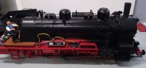
It is quite a detailed, impressive and imposing model. The analog DC version has directional lights, cab light, flickering firebox, wheel/motion lighting and a standard smoke generator. The DCC version also has sound with two triggered by reed switches under the loco. The two reed switches have no function on the analog version but they are fitted nevertheless. Here is the model compared to a prototype:

You might be saying "how come there are no rivets on the side tanks" but riveted tanks were replaced with welded tanks due to excessive leakage. If you're interested in this and the many other design variations of this loco, this site has you covered:
 bundesbahnzeit.de
First question is why not buy the factory installed DCC version? I did consider this but all my other locos have Massoth XL and Massoth sound modules, and I already had a spare XL. One downside to this is that currently there is no Massoth sound project for a BR 94. I am sure the PIKO decoder is perfectly adequate and if you go down this road you can skip the rest of this thread, which is quite long and involves quite a bit of work. If you wanted to "batterify" this you would also have to dismantle the loco.
Anyway to business. First thing it to take a look underneath. As you can see the 0-10-0T is articulated into a 4 wheel motor block at the rear and a 6 wheel motor block at the front. The cylinders are attached to the 6 wheel motor block and the main crank drives the third wheel as on the prototype. Unlike some other PIKO 6 wheel motor blocks it is not itself articulated and has quite a long wheelbase.

This is probably why the PIKO documentation says although this model will run on R1 600 mm radius curves it is recommended to run on larger radius (PIKO R3 or bigger). I haven't found it much of a problem but it does slow down a bit on entering R1 curves.

It doesn't look too bad from the side, but an aeriel view (grotty photo) shows why it might struggle.

Note the wheel pickups are spring loaded "bullets" not brass strip wipers, plus each motor block has a pair of skates. I have removed the skates in later pictures as I feel 10 wheel pickups are probably enough.

Whilst we're underneath, the bulge on the rear motor block houses the two reed switches which can be used to trigger sounds.

CONTINUED IN PART TWO
DR IV BR 94 Steam Loco Buy modeltrains | PIKO Webshop
DR IV BR 94 Steam Loco Buy modeltrains from PIKO | PIKO Webshop ✓ Top quality ✓ Fast shipping ✓ Excellent support
www.piko-shop.de
It is quite a detailed, impressive and imposing model. The analog DC version has directional lights, cab light, flickering firebox, wheel/motion lighting and a standard smoke generator. The DCC version also has sound with two triggered by reed switches under the loco. The two reed switches have no function on the analog version but they are fitted nevertheless. Here is the model compared to a prototype:
You might be saying "how come there are no rivets on the side tanks" but riveted tanks were replaced with welded tanks due to excessive leakage. If you're interested in this and the many other design variations of this loco, this site has you covered:
Die Bundesbahnzeit - Baureihe 94.5
First question is why not buy the factory installed DCC version? I did consider this but all my other locos have Massoth XL and Massoth sound modules, and I already had a spare XL. One downside to this is that currently there is no Massoth sound project for a BR 94. I am sure the PIKO decoder is perfectly adequate and if you go down this road you can skip the rest of this thread, which is quite long and involves quite a bit of work. If you wanted to "batterify" this you would also have to dismantle the loco.
Anyway to business. First thing it to take a look underneath. As you can see the 0-10-0T is articulated into a 4 wheel motor block at the rear and a 6 wheel motor block at the front. The cylinders are attached to the 6 wheel motor block and the main crank drives the third wheel as on the prototype. Unlike some other PIKO 6 wheel motor blocks it is not itself articulated and has quite a long wheelbase.
This is probably why the PIKO documentation says although this model will run on R1 600 mm radius curves it is recommended to run on larger radius (PIKO R3 or bigger). I haven't found it much of a problem but it does slow down a bit on entering R1 curves.
It doesn't look too bad from the side, but an aeriel view (grotty photo) shows why it might struggle.
Note the wheel pickups are spring loaded "bullets" not brass strip wipers, plus each motor block has a pair of skates. I have removed the skates in later pictures as I feel 10 wheel pickups are probably enough.
Whilst we're underneath, the bulge on the rear motor block houses the two reed switches which can be used to trigger sounds.
CONTINUED IN PART TWO
Last edited: