Radio receiver/servo voltages

DGE-Railroad

The Orchard Line
26 Jan 2020
607
89
52
United Kingdom
Best answers
0
Country flag
Could I check something with the electonics whizzes on here please?

I have a live steam loco with an antiquated RC system, the loco electronics (sound and lights) and the R/C are integrated at present and run off a 7.2v battery.

I intend to replace the receiver so I can use the same transmitter I use for my other locos. Others have already had success going this route - put in a new RX, strip the decoder boards out of donor servos and wire the servo board outputs into the loom for the existing motors for the speed regulator and valve control.

The issue I have is that 7.2v. That's high(er) voltage receiver and servo territory. I need to keep those motors supplied with 7.2v or they're going to be really slow.
The donor servos I'm using are high voltate so can pass the 7.2v without issue. The only receivers that will bind with my transmitter though, are the lower 4.8v type.

So....

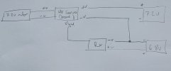
Am I correct in thinking I can supply 4.8v to the RX, keep the signal wires from the RX going to the servo boards, but split out the servo board power and take that straight from the OEM 7.2v battery?
Logic tells me that should be fine. Can anyone confirm it?
 
  • Like
Reactions: 1 user

PhilP

G Scale, 7/8th's, Electronics
5 Jun 2013
33,566
3,521
Nottingham
Best answers
0
Country flag
Probably..

There may be problems if the servo's are expecting other than the (now fairly standard) pulse-width for control.
Make sure the battery negative (ground) is common across all the devices.

PhilP.
 

DGE-Railroad

The Orchard Line
26 Jan 2020
607
89
52
United Kingdom
Best answers
0
Country flag
Probably..

There may be problems if the servo's are expecting other than the (now fairly standard) pulse-width for control.
Make sure the battery negative (ground) is common across all the devices.

PhilP.

Thanks Phil. I'll give it a try.
Thanks too for the recommendation of the common ground. I would probably have overlooked that.
 

PhilP

G Scale, 7/8th's, Electronics
5 Jun 2013
33,566
3,521
Nottingham
Best answers
0
Country flag
Just to be sure on this:
You have a live-steam loco? - The left-hand '7.2V motor' is slightly confusing? Is it a servo?

Are you *sure* there is not a regulator on the original board? - It could be the servo's are the de-facto 5V?

Answers to the above, and I think I might need to correct the diagram slightly.. :wondering::nerd:

(Some photo's would help.. ) :):nod:

PhilP.
 

DGE-Railroad

The Orchard Line
26 Jan 2020
607
89
52
United Kingdom
Best answers
0
Country flag
Just to be sure on this:
You have a live-steam loco? - The left-hand '7.2V motor' is slightly confusing? Is it a servo?

Are you *sure* there is not a regulator on the original board? - It could be the servo's are the de-facto 5V?

Answers to the above, and I think I might need to correct the diagram slightly.. :wondering::nerd:

(Some photo's would help.. ) :):nod:

PhilP.


That's correct Phil. It has a proprietary R/C system, rather than an aftermarket one.
The loco has a DC motor operating (through what I imagine is a planetary gearbox of some sort) the valvegear and another operating the regulator.
These motors have limit switches to limit their travel.
The R/C electronics are in the tender and each motor has a pos/neg motor connection.
The motors are sent either +7.2v or -7.2v dependant on the direction they need to move (certainly that's the measurement at the loco/tender loom) I will try and tap a multimeter directly to the motor to confirm that voltage is what is being received there.
I can't get to the loco board easily but I *believe* it's essentially a distribution board and circuitry to have the limit-switches cut the motor supply when closed.

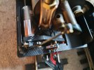
Here's the regulator motor where the full-throttle limit switch can be seen at the bottom
20200930_131901.jpg
 

DGE-Railroad

The Orchard Line
26 Jan 2020
607
89
52
United Kingdom
Best answers
0
Country flag
Just checked at the motor. It's receiving 6.8v positive or negative depending on whether the regulator is opened or closed
 

PhilP

G Scale, 7/8th's, Electronics
5 Jun 2013
33,566
3,521
Nottingham
Best answers
0
Country flag
Just checked at the motor. It's receiving 6.8v positive or negative depending on whether the regulator is opened or closed

Thanks for that.. A definite meld of electronics and mechanics. :)

Give me a few minutes.. - A warm 'lunch' going cold, and boiler in bits.. ;)
 
  • Haha
Reactions: 1 user

PhilP

G Scale, 7/8th's, Electronics
5 Jun 2013
33,566
3,521
Nottingham
Best answers
0
Country flag
Right.. Just my coffee to finish..

Actually, it would only be if you were trying to use modern servo's you would need '4.8V', and even then, the receiver would give that out..
Something like a RCT-Rx102 (Deltang) or RCT-MR001(a or b) can have a supply voltage between 3.5 - 10.0 Volts, so could connect straight to the battery. :)

if you used modern servo's, then the outputs from the new Rx would present signal and 5V power anyway.

You will need two signal inputs into you controller board, though:
Pin 1 - Throttle
Pin 3 - Direction
Supposing you would be 'low-off', with separate control for direction.

** The above pins / channels would depend on the radio gear you decided to use.

PhilP.
Amazing what you can do after something warm to eat, and a coffee! :):nerd::nod::nod:
 
  • Like
Reactions: 1 user

DGE-Railroad

The Orchard Line
26 Jan 2020
607
89
52
United Kingdom
Best answers
0
Country flag
:D

Thanks very much Phil.
My existing transmitter is a cheapy Code RC thing which came with the Roundhouse. I may look some day at moving both this and the Roundhouse over to a Deltang/Fosworks setup as I don't think the stick transmitters are particularly natural-feeling for loco control :) (although I don't think the Fosworks receivers go over the 5v threshold, which may rule them out)

That said, whilst you were refuelling, I did a bit of experimenting.

Here's a test with my normal low-voltage code rc receiver, driving the donor servo board, with the motor output from it fed directly into the regulator pins on the loco loom.
It all works as it should, albeit a bit slowly due to the motor running slower at the lower voltage. That said, it's possibly no bad thing for scale running, so I could just stick with that and a 4.8v 'RC' battery, being lazy and keeping the 7.2v for the flame ignition and headlamp...

Please excuse the squeaks in the background from my son :)
Servo testing

Curiously, when I pulled the +v lead from the receiver servo plug and fed that to the 7.2v battery positive, I got nothing with the servo board hooked up to the multimeter as a test
 

PhilP

G Scale, 7/8th's, Electronics
5 Jun 2013
33,566
3,521
Nottingham
Best answers
0
Country flag
You can always use one of these to drop your 7.2V. battery volts for your new Rx:


PhilP.
 

PhilP

G Scale, 7/8th's, Electronics
5 Jun 2013
33,566
3,521
Nottingham
Best answers
0
Country flag
InOtherNews:

We have ignition! :):nerd::party::party:

£3.29 for the thermocouple, and 40 minutes including there and back to collect.. :rock::rock:
 
  • Like
Reactions: 1 user

DGE-Railroad

The Orchard Line
26 Jan 2020
607
89
52
United Kingdom
Best answers
0
Country flag
InOtherNews:

We have ignition! :):nerd::party::party:

£3.29 for the thermocouple, and 40 minutes including there and back to collect.. :rock::rock:


Hooray!!
You can celebrate with a warm house this evening, to counteract this rubbish damp weather!
 

PhilP

G Scale, 7/8th's, Electronics
5 Jun 2013
33,566
3,521
Nottingham
Best answers
0
Country flag
Hooray!!
You can celebrate with a warm house this evening, to counteract this rubbish damp weather!

And Brownie-points, with SW..

I have also been able to replicate a fault on a transmitter.. Not a cure, but I can make the fault happen, and then fix it..

Unfortunately, the transmitter core will need replacing, as I am unable to find/repair the fault. :(:mad:
 

Fred2179G

Registered
20 Apr 2017
1,059
186
USA
Best answers
0
Country flag
albeit a bit slowly due to the motor running slower at the lower voltage. That said, it's possibly no bad thing for scale running, so I could just stick with that and a 4.8v 'RC' battery,
My understanding is that servos and RXs operate from 4.8V (e.g. 4x1.2V Lion) up to 6V (e.g. 4x 1.5V regular battery.) 6V will not hurt anything, and will improve your performance. Mine certainly don't opject to 6V when I use ordinary (not rechargeable) batteries.

I would also recommend looking at the RCS range of TX and RX. They are small handheld knob systems using DSM2, which gives you a wide range of RX options. The current range uses the Deltang TX chips, I think. www.rcs-rc.com.
 
  • Like
Reactions: 1 user

DGE-Railroad

The Orchard Line
26 Jan 2020
607
89
52
United Kingdom
Best answers
0
Country flag
Good point Fred. I can probably push the voltage up to 6v.

I've been doing some experimenting with my 2-stick transmitter. It's set up in the same manner essentially as the Deltang/RCS/Fosworks offerings, albeit without the benfit of the more logical rotary control.

So I have ;
Unsprung Left stick: regulator. Fully down is fully shut. Fully up is fully open
Sprung right stick: valve. push right for forwards, push left for reverse.

The servo board approach works fine for the valve (direction) stick. The stick is usually at centre which corresponds to zero volts (you calibrate wiith the stick at centre and twiddle the servo board pot until the board output is 0v) then pushing the stick right will gives +Vmax. Pushing the stick left gives -Vmax.
This is all good news for the aristo motor circuitry - it expects +Vmax or -Vmax and uses mechanical limit switches to cut this when the travel limit is reached.

The problem for the regulator is that we don't care about mid-stick . We want any downward stick movement to correspond to -Vmax and any upwards stick movement to corresponds to +Vmax. You can't calibrate the servo board for that (unless there's something trick you can do in thr transmitter)

The result is a slightly strange feeling control - the regulator won't open until the stick is past midpoint and won't close until its below midpoint. In order to hold a half throttle position you'd need to move the regulator and then find midpoint on the stick in order to keep a 0v output from the board.

After playing around I've opted to swap the controls around for this loco - the unsprung left stick will be fwd/reverse and the sprung right stick will open the regulator when pushed right and close it when pushed left. Letting it spring back to rhe mid position keeps the current throttle position.

I may swap the servos on the Roundhouse to match as it feels fairly natural in operation

I don't think this motor-control approach with servo-boards would work as well for anyone running the RCS/Deltang/Fosworks type dual rotary knob type of transmitter. For those I think you'd want to swap out the regulator motor for a servo. That wouldn't be too hard to do; you'd just need a small pair of blocks to mount it, splice this servos negative lead into the regular valve motor negative and push the regulator signal and power through the two regulator wires in the loco/tender loom.