Is anyone familiar with the “starting delay circuit” that every older LGB F7 A unit has? This feature prevents the F7 from moving until there are about seven volts on the track, and the reason for this feature is that it allows the sound (which comes from the B unit) to turn on before the engine starts to move. I am trying to get a basic understanding of what exactly the starting delay circuit is and how it works. Like, is it on the F7’s main circuit board? Is it in the motors? Does it have anything to do with the metal bars that are in the F7’s motor blocks? Plus, is there anything that could cause the starting delay circuit to fail?
You are using an out of date browser. It may not display this or other websites correctly.
You should upgrade or use an alternative browser.
You should upgrade or use an alternative browser.
Questions about LGB F7 “Starting Delay Circuit” feature
- Thread starter alex19881
- Start date
It will be on the board. - A motor is just that.
The strips in the motor-block, just connect things together.
The circuit is quite complex, with a number of transistors, so there could be a problem.
Massoth did do a delay circuit, but I think they have stopped?
Last one(s) I got came from the US. - Took some hunting.
PhilP
The strips in the motor-block, just connect things together.
The circuit is quite complex, with a number of transistors, so there could be a problem.
Massoth did do a delay circuit, but I think they have stopped?
Last one(s) I got came from the US. - Took some hunting.
PhilP
Not easily..
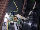
A guess (amongst others) would be the orangey-yellow thing at the top of the board, and the big inductor.
But there will be more to it than just those.
It is a different circuit to the Massoth unit.
I assume you have a problem with one of these?
PhilP.
A guess (amongst others) would be the orangey-yellow thing at the top of the board, and the big inductor.
But there will be more to it than just those.
It is a different circuit to the Massoth unit.
I assume you have a problem with one of these?
PhilP.
Not easily..
A guess (amongst others) would be the orangey-yellow thing at the top of the board, and the big inductor.
But there will be more to it than just those.
It is a different circuit to the Massoth unit.
I assume you have a problem with one of these?
PhilP.
About seven years ago, the starting delay circuit in an LGB F7 that I owned stopped working (the engine would move at about one or two volts). And this happened after I had removed one of the wheel sets to clean them. In any case, a few weeks ago, I bought another LGB F7 (it was brand new, had never been run). I ended up bringing it to a friend of mine who fixes model trains, given that the traction tire needed to be replaced. He ended up replacing all of the engine’s gears, given that three of them had cracks. Afterwards, I brought the engine home, and the starting delay circuit had stopped working, just as the one in my other F7 had. I ended up repositioning the metal strips that are in the motor blocks, which fixed the problem (the engine now will not move until I give it at least seven volts ). This is very strange and confusing, and I am trying to figure out why this happened.
Also, keep in mind that both LGB F7s are old (they were made in the late 1990s or the early 2000s). They are not the LGB F7s that Marklin manufactures.
Just to clarify, if the metal strips had been positioned incorrectly, track voltage would have gone directly to the motors, rather than first going to the circuit board?The strips in the motor-blocks 'common' (connect together) the carbon brushes and skates..
If in the wrong position, obviously there was a connection to a motor connection from track-power. - This would bypass the delay circuit.
PhilP.
Yes, there are brass strips where the skates are in the block. These span two of the longitudinal locations that the long strips can be in. - They can be in different positions in different motor-blocks.Just to clarify, if the metal strips had been positioned incorrectly, track voltage would have gone directly to the motors, rather than first going to the circuit board?
If they are in the wrong position, then they will bridge from track-power to the motor-pins.
PhilP.
Philip, thank you for your insight into this. I am glad to finally know what caused this problem.Yes, there are brass strips where the skates are in the block. These span two of the longitudinal locations that the long strips can be in. - They can be in different positions in different motor-blocks.
If they are in the wrong position, then they will bridge from track-power to the motor-pins.
PhilP.
One other thing - if track voltage was going directly to the motors, rather than first going to the main board, wouldn’t this result in the engine’s headlight not working? My understanding is that track voltage must go to the engine’s main board in order to get to the headlight, given that there is a connection between the main board and the board for the headlight.
Correct.
Power would be back-fed into the board via the motor connections. - Working out what will and won't work under these conditions, can be tricky.
From memory, only one motor-wire is affected by the delay circuit. - At least, that is the way the Massoth board works.
PhilP.
Power would be back-fed into the board via the motor connections. - Working out what will and won't work under these conditions, can be tricky.
From memory, only one motor-wire is affected by the delay circuit. - At least, that is the way the Massoth board works.
PhilP.
The delay circuit is on the main board.
Depending on how the strips were positioned, track power was getting to the motor.
This would also travel 'backwards' into the main board via the motor wires connected to the pins on the motor block.
There was obviously a path back through the circuitry on the board, to the regulator which supplies 5V to the lights. - It would take very little current to 'leak' through to power the lights.
If I am remembering correctly, and in the analogue model, track and motor are connected anyway, then it would be even easier for there to be a path through the circuitry to power the headlights.
Without a schematic (circuit diagram) it is not easy to work this out.
PhilP.
Philip, I apologize for all of the questions, and I promise that this will be the last one. If voltage was traveling “backwards” to the main board, this means that it was traveling through the negative wire, rather than through the positive wire, correct? And could this have caused any harm to be done to the main board?The delay circuit is on the main board.
Depending on how the strips were positioned, track power was getting to the motor.
This would also travel 'backwards' into the main board via the motor wires connected to the pins on the motor block.
There was obviously a path back through the circuitry on the board, to the regulator which supplies 5V to the lights. - It would take very little current to 'leak' through to power the lights.
If I am remembering correctly, and in the analogue model, track and motor are connected anyway, then it would be even easier for there to be a path through the circuitry to power the headlights.
Without a schematic (circuit diagram) it is not easy to work this out.
PhilP.
Once again, thank you for your insight into this.
Due to the way things work, if a current is flowing 'up' a red wire, then somewhere an equal current will be flowing 'down' another.Philip, I apologize for all of the questions, and I promise that this will be the last one. If voltage was traveling “backwards” to the main board, this means that it was traveling through the negative wire, rather than through the positive wire, correct? And could this have caused any harm to be done to the main board?
Once again, thank you for your insight into this.
I have it on good authority, that electrons are color-blind, so don't care what color the wire is.

If there is a higher potential (voltage) at one end of a wire than another, then if nothing is connected, the whole wire will be at that higher 'voltage'.
If there is a path to 'earth' (or something more negative) then a current will flow.
The above are 'lies to children' and it gets very complicated very quickly..
Example:
Electrons don't flow. They are lazy and 'drift'.. The 'thing' we call 'current' flows..
It would actually take about a century for an electron to drift across a Trans-Atlantic cable. - If the electron could be bothered.
But (another lie to children) if you 'push' an electron into one end of the cable, one pops out at the other..
But all the above will be like finger-nails on a blackboard, to a Physicist.

As to damaging the board.. If it worked afterwards, then no.
But luck more than anything.
PhilP.
Similar threads
- Replies
- 15
- Views
- 800
- Replies
- 4
- Views
- 389
- Replies
- 11
- Views
- 1K
- Replies
- 7
- Views
- 661