Points indicator panel

timichl100

Registered
26 Jan 2024
16
0
64
Illinois
Best answers
0
Country flag
A little background; I am using (2) Piko 35260 Switch Control boxes on my layout to control 8 points. Three of the points are in the shed train yard. The other 5 are on the layout but some are difficult to see from the control box location. I have seen Switch control panels with LED indicators to show the direction the switch is in on smaller scale layouts but have not seen anything comparable for G scale. Is there a product that can be connected to the Piko switch control box that can indicate the switch direction for each individual switch, or is there a circuit design I can add to the switches to power on LEDs showing direction on a map? I'm hoping this makes sense.

Thanks
Tim
 

Software Tools

Registered
18 Jan 2013
311
56
Sydney, Australia
Best answers
0
Country flag
Is there a product that can be connected to the Piko switch control box that can indicate the switch direction for each individual switch, or is there a circuit design I can add to the switches to power on LEDs showing direction on a map? I'm hoping this makes sense.

Well, there are a couple of things here.... firstly, do you need a "simple indicator" or a "tally indicator"? A simple indicator just tells you the button was pressed, while a tally indicator will confirm the point has actually thrown to the desired position.

Tally indicators need more "stuff" but are better operationally.... and if that is what you do need, what devices are you using the throw those remote points?
 

timichl100

Registered
26 Jan 2024
16
0
64
Illinois
Best answers
0
Country flag
Well, there are a couple of things here.... firstly, do you need a "simple indicator" or a "tally indicator"? A simple indicator just tells you the button was pressed, while a tally indicator will confirm the point has actually thrown to the desired position.

Tally indicators need more "stuff" but are better operationally.... and if that is what you do need, what devices are you using the throw those remote points?
A simple tally indicator should work fine. More specifically, I would like to have a light indicating which direction the point is set. Using a light on each leg, the run light would be on and the other would be off. With the Piko switch box uses momentary switches so I'm guessing a latching relay would be needed to keep power to the light. If there are suggestions, they would be welcome.
 

Software Tools

Registered
18 Jan 2013
311
56
Sydney, Australia
Best answers
0
Country flag
With the Piko switch box uses momentary switches so I'm guessing a latching relay would be needed to keep power to the light. If there are suggestions, they would be welcome


Are you using EPL (or similar) two wire point motors, or some other type of point motor?
 

Paul M

Registered
25 Oct 2016
11,938
1,705
61
Royston
Best answers
0
Country flag
Surely it would be a similar set up to working light signals
 

dunnyrail

DOGS, Garden Railways, Steam Trains, Jive Dancing,
Staff member
GSC Moderator
25 Oct 2009
26,225
5,000
75
St.Neots Cambridgeshire UK
Best answers
0
Country flag
As Software Tools Software Tools says an LGB point motor can have an auxiliary switch fitted which can then be used to indicate the settings you require. But with possibly long lengths of wiring! If you use the Point Switch auxiliary you can be pretty certain the blades have moved across ok, but with the wiring on a switch in your panel you only know you have thrown the switch.
 

IanMTrain

Registered
7 Jul 2021
8
0
69
Wallingford
Best answers
0
Country flag
A simple tally indicator should work fine. More specifically, I would like to have a light indicating which direction the point is set. Using a light on each leg, the run light would be on and the other would be off. With the Piko switch box uses momentary switches so I'm guessing a latching relay would be needed to keep power to the light. If there are suggestions, they would be welcome.
Hi Tim

I am in the process of building a similar panel for LGB points on my Wallingford Industrial Rail Ltd. (WIRL). I designed a small pcb to pickup the momentary pulse to the switch motor to set or reset a DP latching relay so I have lights on the main and switched track. I have been using LGB switch boxes but will swap them for DPDT momentary switches on the control panel.

There is a YT video of a demo of the circuit and PCB on the WIRL channel on YT - not a great video I hasten to add as I am still struggling to juggle the mechanics of the recording with the “doing”.
Should get you to the video.

If you think these approach would be useful to you I will be happy to share the design and gerber file for the pcb.

Ian Makin
WIRL
 

timichl100

Registered
26 Jan 2024
16
0
64
Illinois
Best answers
0
Country flag
Hi Tim

I am in the process of building a similar panel for LGB points on my Wallingford Industrial Rail Ltd. (WIRL). I designed a small pcb to pickup the momentary pulse to the switch motor to set or reset a DP latching relay so I have lights on the main and switched track. I have been using LGB switch boxes but will swap them for DPDT momentary switches on the control panel.

There is a YT video of a demo of the circuit and PCB on the WIRL channel on YT - not a great video I hasten to add as I am still struggling to juggle the mechanics of the recording with the “doing”.
Should get you to the video.

If you think these approach would be useful to you I will be happy to share the design and gerber file for the pcb.

Ian Makin
WIRL
Ian, This looks exactly like what I am looking for. I would appreciate a copy of the design to try it out if you can part with it. Thank you for the effort.

Tim
 

IanMTrain

Registered
7 Jul 2021
8
0
69
Wallingford
Best answers
0
Country flag
Hi Tim

Certainly happy to share the design and component list. You can try it out on a breadboard. The biggest cost is the relay.

I am on holiday with grandkids at present. I’ll have a dig in the iPad to see if I have the files here (Kuala Lumpur). If not I can send when I get home about 22 Feb.

I was in the middle of a redesign of the pcb when we came away to (i) include pads for resistors for the LEDS on the board, and (ii) change the connectors to and from the board. As I said in the video I made a mistake in the design by having surface mount sockets and also the selected sockets were much too small for outdoors use. So if you want to have the same sort of pcb arrangement, I can share that in early March.

What voltage are the switch motors? The relays seem to cope with a wide range but it is probably worth picking one that matches your system.

Best
Ianm
 

Software Tools

Registered
18 Jan 2013
311
56
Sydney, Australia
Best answers
0
Country flag
IFF you are using EPL (or similar) two wire point motors that work on the basis of reversing the polarity of the current flow through the two wire circuit, you can use readily available and inexpensive polarised latching relay and a couple of LEDs (with a dropping resistor) to provide to a "simple indicator" (that's a count of 4 components).

So, again, what type of point motors are you using?
 

timichl100

Registered
26 Jan 2024
16
0
64
Illinois
Best answers
0
Country flag
Thanks to everyone for the recommendations. For my layout I am using standard two wire EPL motors. Some are Piko and most are LGB. I have been powering the switch boxes with the 24V AC output from my Bridgeworks Magnum transformer. I recently changed over to Blunami cards in my locos and was going to power the track with an 18V transformer and tap the switch box power off of that since the switch box is rated for AC or DC input. I will also be re-wiring for a master "kill" switch for the layout.

I was thinking about the simpler circuit with the latching relay for the tally indicator but I wasn't sure what the list of components would be or how to wire them up.
 

Software Tools

Registered
18 Jan 2013
311
56
Sydney, Australia
Best answers
0
Country flag
layout.

I was thinking about the simpler circuit with the latching relay for the tally indicator but I wasn't sure what the list of components would be or how to wire them up.

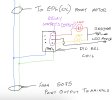
This is a rough diagram but hopefully will give you the idea on how to connect the parts up. You will need a polarised latching relay.... since it is only switch a low current for the LEDs it doesn't need to be a large high-current relay, an inexpensive DIL (dual in line) package will be fine and you should be able to source one in the GBP 2 to GBP 5 range. Here's a current eBay listing for a suitable relay (but there are numerous suitable types around).


The relay will "change" when the impulse from the 5075 goes to the point and will stay on that setting until a different polarity impulse from the 5075 arrives to change the point to its alternative position..

The LEDs can be any size or colour that suits your purpose and the value of the dropping resistor can be determined is the usual way which has been described here numerous times. You will need a suitable power source for the LEDs.

You will need to do a bit of playing around with the polarity of the connection to the relay coil to get the correct LED for your purposes to illuminate for the first installation, but once you have worked it out you can just duplicate for the remaining installations.


IMG_6968.jpeg
 
  • Like
Reactions: 1 user

IanMTrain

Registered
7 Jul 2021
8
0
69
Wallingford
Best answers
0
Country flag
This is a rough diagram but hopefully will give you the idea on how to connect the parts up. You will need a polarised latching relay.... since it is only switch a low current for the LEDs it doesn't need to be a large high-current relay, an inexpensive DIL (dual in line) package will be fine and you should be able to source one in the GBP 2 to GBP 5 range. Here's a current eBay listing for a suitable relay (but there are numerous suitable types around).


The relay will "change" when the impulse from the 5075 goes to the point and will stay on that setting until a different polarity impulse from the 5075 arrives to change the point to its alternative position..

The LEDs can be any size or colour that suits your purpose and the value of the dropping resistor can be determined is the usual way which has been described here numerous times. You will need a suitable power source for the LEDs.

You will need to do a bit of playing around with the polarity of the connection to the relay coil to get the correct LED for your purposes to illuminate for the first installation, but once you have worked it out you can just duplicate for the remaining installations.


View attachment 323694
Hi

This is an elegant solution without all the fussy stuff in the (still untested real world) WIRL setup. If I understand the relay here it switches from set to reset with the change in polarity of the pulse to the point motor? I tried something similar with a relay but it got really unhappy with the reversing polarity - and stopped working fairly instantly! I’ll have another go when I get home, although now I have the cards and relays I’ll probably stick with the WIRL plan.

How does the simple relay cope with switch bounce?

Cheers
Ianm
 

Software Tools

Registered
18 Jan 2013
311
56
Sydney, Australia
Best answers
0
Country flag
How does the simple relay cope with switch bounce?

Since it is a latching relay, switch bounce is not an issue.

BTW, LGB used this approach in the first few iterations of the 2040 (RhB Crocodile) for switching the directional lights.
 

timichl100

Registered
26 Jan 2024
16
0
64
Illinois
Best answers
0
Country flag
Since it is a latching relay, switch bounce is not an issue.

BTW, LGB used this approach in the first few iterations of the 2040 (RhB Crocodile) for switching the directional lights.
This weekend I will give it a try. Ordered a couple of the relays to test.
 

timichl100

Registered
26 Jan 2024
16
0
64
Illinois
Best answers
0
Country flag
This weekend I will give it a try. Ordered a couple of the relays to test.
I received the relays to test the circuit and once I was able to determine the pin configuration it worked well with the Piko switch. The only issue I had in testing was that I had to hold the momentary switch button a little longer than just a quick press to get the relay to latch properly. I'm looking forward to building it up.
 

IanMTrain

Registered
7 Jul 2021
8
0
69
Wallingford
Best answers
0
Country flag
I received the relays to test the circuit and once I was able to determine the pin configuration it worked well with the Piko switch. The only issue I had in testing was that I had to hold the momentary switch button a little longer than just a quick press to get the relay to latch properly. I'm looking forward to building it up.
Hi Tim

That’s great news. It is a lot simpler solution than my one. Still I will have lots of fun soldering the circuit boards up and wiggling them into place……

Cheers
Ianm
WIRL
 

IanMTrain

Registered
7 Jul 2021
8
0
69
Wallingford
Best answers
0
Country flag
Hi Tim


I got a similar relay and tested it this morning - I found (like you) I had to hold the momentary switch a bit longer than with the WIRL relay pcb. Also, even then, it would often not latch as reliably as I wanted. I will continue with the WIRL circuit for now, I think. I may add a little segment on the simple relay arrangement in the next instalment on teh control panel for Pit Head Halt, perhaps including a debounce circuit to see if that helps the relay latch more reliably.

Cheers
Ian M