Piko BR 64 Review and Upgrade

P A D

Registered
26 Aug 2020
42
25
70
Leeds
Best answers
0
Country flag
Thanks Jon,
I hope I can continue to gast your flabber as the thread continues.

So, using the shanks of a grinding burr to get a consistent bend, the the wire is looped in between the sand pipes, to be located on a strip of plasticard glued to the underside of the sand gun body.
20200927_192600.jpg

The wires are then adjusted and glued to the plastic strip.
20200927_192527.jpg

And then trimmed with side cutters.
20200927_111130.jpg

One sided done.
20200927_111144.jpg

To complete the modifications to the sand dome, the missing grab rails were added using 0.6mm copper wire. The top edge of the side pieces needed filing to clear the excess grab rail wire inside the dome, otherwise it won't locate properly.
20200927_192358.jpg

And with the three parts located on the boiler. They are not glued yet, as other pipes need replacing first and I will need to remove the sand pipes to do that.
20200927_192258.jpg

In preparation for refitting, I added some details to the plastic pipe work. First the valve behind the preheater on the right hand side had the hand wheel at the bottom replaced with an etched brass one I had in the spares box.
20200927_192035.jpg

And I added the missing operating lever and condensate drain pipe to the whistle valve.
20200927_192128.jpg

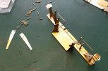
The too large gap between the top flanges on the steam heating coupling offended my sensibilities, so I sawed through the gap, filed off the excess, drilled both part and added a length of 0.8mm copper wire to reinforce the joint before re glueing together. Here are the parts with the pin glued in "pipe" ready for trimming.
20200927_192001.jpg

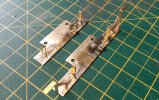
I then went off on a tangent and made a start on the missing under buffer details. First I made some base plates on which to fix the details, which will be located under the buffer beams via the bufferbeam fixing screws. This will allow easy removal should I ever need to run the loco on tight radius curves using the Piko tension lock coupling. The rear plate on the left, has the mounting for the steam heating pipe and the stowage brackets for the brake pipes. The front one has the same, plus the foot step brackets. Back in the comfort zone with these parts which are all fixed with 145 degree solder.
20200928_201810.jpg

Here's the front plate after adding the footsteps, which again, came from the spares box.
20200928_201649.jpg

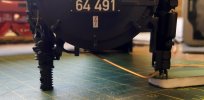
Here's a view from the underside showing how the steam heating coupling is mounted. It's a firm push fit in the bracket for now, but ultimately, it will be super glued. I daren't go near it with the hot stick, lest I melt the plastic parts!
20200928_201606.jpg

And with both couplings inserted.
20200928_201530.jpg

There are still some grab rails to be added, but here are the plates test fitted.
20200928_201247.jpg

I will file back the front edges on the plates to disguise them, but they will also be less noticeable after painting.
20200928_201013.jpg

Some adjustment of the base plate will be necessary to get the steps to align correctly, but so far, I'm pleased with the result.
20200928_200700.jpg


20200928_200307.jpg

Cheers,
Peter
 

Attachments

  • 20200928_201810.jpg
    20200928_201810.jpg
    654.9 KB · Views: 0

Zerogee

Clencher's Bogleman
25 Oct 2009
17,351
1,723
North Essex
Best answers
0
Country flag
'Tis true, my ghast has seldom been so flabbered..... :rofl:

Jon.
 

P A D

Registered
26 Aug 2020
42
25
70
Leeds
Best answers
0
Country flag
I lost some time today backtracking on the brake pipe valve handles. Looking a photos, they needed to be longer and cranked at the bottom. It's amazing how well super glue sticks metal to plastic when you want to remove something. I finally got the four of them off and replaced them but it took a lot of time for such simple items.

Back on the lower bufferbeam detail, I added the grab handles from 0.8mm copper wire, the rear ones having to be mounted on outriggers, as I made the base plate too narrow.
20200929_194159.jpg

When working on etched brass kits I would always use brass wire for grab rails and piping, but having used copper wire on the BR 86, I find it is much easier to work with and easier to correct mistakes if you get a bend in the wrong place. Brass rod is much better for long straight runs such as hand rails, as it is less likely to be bent when handling the model.
20200929_194140.jpg

The brake pipes were formed from 1.5mm copper wire. The ends were flatten to represent the coupling and to locate in the stowage brackets
20200929_160838.jpg

Here's how they locate in the stowage brackets.
20200929_185543.jpg

So I can remove them if required they are only a push fit in their mountings on the buffer beam. To give the stud at the top more purchase in the locating hole, I added a piece of 80 thou plasticard to the rear of the beam and drilled through.
20200929_185520.jpg

Flanges for the top and bottom ends of the pipes were made from 0.6mm copper wire as before. Here are the plates trial fitted under the buffer beams. First the front one.20200929_182836.jpg

And the rear. You can see the replacement handles added to the brake valves. On the prototype, the loop on the end of the steam heating coupling was stowed on the grab rail by a hook, yet to be added. I filed and rubbed down the front edges of the base plates by about 1mm and hopefully when they are painted, they will be less visible.
20200929_182606.jpg


It's now starting to look more business like under the bufferbeams and it just needs the missing front end of the frames and guard irons to finish it off.
20200929_182400.jpg

By the way, I came across this detailing set for the BR 64 which would save some time, but at £53 it's very expensive for a few plastic parts.

Cheers,
Petef
 
  • Like
Reactions: 1 users

phils2um

Phil S
11 Sep 2015
1,522
423
Ann Arbor, Michigan
Country
United-States
Best answers
0
Country flag
Amazing work! It keeps getting better and better. Well done.
 
  • Like
Reactions: 1 user

P A D

Registered
26 Aug 2020
42
25
70
Leeds
Best answers
0
Country flag
Many thanks Phil.

Moving on to the guard irons, these were made from 4 length of 5mm wide brass strip laminated together, then fettled to shape with the file. Once happy with the shape, holes were drilled through the laminate for the fixing rivets and then the irons were desoldered to separate. Here's the laminate ready for drilling. It's much easier and quicker to do the 4 irons together as you only have to make the shape once and they are then all the same.
20200930_170807.jpg

And after drilling and the front pair installed. I first soldered the irons to the "frames", then drilled through the holes before inserting and soldering the rivets.20200930_170749.jpg

Both sets done and the rivets trimmed and filed flush on the inside. To improve the appearance, I super glued a piece of 20 thou plasticard to the inside of the irons, then trimmed with side cutters and filed to match the brass. This was easier and safer than doing it with brass strip and risking desoldering some of the parts.
20201001_131140.jpg

After priming, I've made a start on painting the two units, as well as adding the red to the steam heating coupling.
20201001_180418.jpg

I'm just brush painting these and further coats are required.
20201001_180449.jpg

The rear unit fits nicely and the pony truck can pivot unhindered. However, the flanges on the front wheels foul the guard irons, in spite of fettling them as much as possible. If I file them to clear they will be too narrow and spindly. Moving them forward on the base plate will position them under the buffer beam when they should be flush to the rear edge. To overcome this I've decided to further modify the truck by shortening the support beam. First I scribed a line with the scrawker where the cut was to be made. I deepended the groove by giving several passes and then sawed through with a razor saw to compete the cut.20201001_090857.jpg

I then carefully filed back the arm to reduce the length by 1mm and removed the paint inside the parts with cellulose thinners. The two parts were then rejoined with an 80 thou strip of plasticard on the inside at the top, to reinforce the super glued joint. I overlooked to take a photo but will add one in the next post. I've tested the truck under the loco and the wheel flanges now clear the guard irons.
20201001_091222.jpg

Cheers,
Peter
 

Attachments

  • 20200930_170725.jpg
    20200930_170725.jpg
    382.7 KB · Views: 0

P A D

Registered
26 Aug 2020
42
25
70
Leeds
Best answers
0
Country flag
So, here's the reassembled pony truck.
20201002_180651.jpg

And the reinforcing strip on the inside from 80 thou plasticard.
20201002_180640.jpg

I mentioned earlier that the model comes with some separate detail parts to be fitted by the owner as required. Amongst these are the stanchions and grab rings for the upper platforms at the front, but unfortunately Piko do not include the shorter ones on top of the tanks. As these were being made from brass rod and copper wire, I thought it prudent to replace the larger plastic ones as well. Top right is one of the plastic ones, with the replacements below (1.0mm brass rod for the stanchions and 1.0mm copper wire for the grab rings). The shorter ones on the left were scaled from a photo. The tape holds the rod steady and the rings are lined up with the joint in line with the rod and are held in place with a small length of wood and then soldered.
20201002_201013.jpg

Here they are after painting and fitted in place. The upper ones are glued but the lower ones are just pushed fit for now. I'll glue them on later when the boiler is back in place.
20201002_170415.jpg

I added the feet to the upper stanchions from some spare etchings. They don't match the lower ones, but better than nothing.
20201002_170434.jpg

To complete the buffer beam detail sub sections, the coupling hook oil pot and pipe was added to the front buffer beam. It was made by cutting down a resin cast 3 feed oil pot from the spares box, mounted on a brass backing plate with the pipe made from 0.4mm copper wire. A short length of of 0.8mm brass rod was soldered to the rear of the plate, for mounting in a hole drilled in the buffer base plate.
20201003_111333.jpg

And in place on the buffer beam. I took the opportunity to thin down the left hand buffer heads, front and back as well.
20201003_113521.jpg
20201003_113509.jpg

Further work was done on the steam heating couplings, with the addition of the perforated plates to the lower sections.
20201003_134338.jpg

Here are the steam heating couplings along with the brake pipes and smokebox drain pipe after painting.
20201003_151904.jpg

And the front buffer beam back on the loco with all the details in place including the hook on the grab rail for stowing the steam heating coupling.
20201003_162639.jpg

With the work on the chassis completed, I went back to adding the missing boiler details. Here I have added the operating lever and linkage to the whistle.
20201003_181502.jpg

Cheers,
Peter
 

P A D

Registered
26 Aug 2020
42
25
70
Leeds
Best answers
0
Country flag
At the front of the boiler I've added some missing pipe work to the valve behind the preheater on the right hand side.
20201004_185811.jpg

The Piko compressor and water pump are very nice representations of the real things, but there is still some additional detail that can be added to improve them. Here are some photos from the internet of the real thing, on the preserved BR86, 86 283. This is the compressor.
br_86_1_ref_comp1.jpg

And here, the water pump.
br_86_1_ref_kt250_1.jpg

This is a view of the lower part to the water pump.br_86_1_ref_kt250_2.jpg

Here are the Piko items after removal from their mountings on the boiler.
20201004_094327.jpg

They can be dissmantled to give these separate parts, which make it easier to work on them.
20201004_190951.jpg

First I removed one of the three enclosed segments which surround the piston rod. There should be two open and two closed, but on the Piko moulding, only the segment facing right is open.
20201004_190854.jpg

Here it is after fitting various oil pipes, unions and an additional air filter (the large white thing at the rear.
20201004_190229.jpg

And a view from the front showing the oil pipe runs. I believe the large pipe at the bottom, which will loop behind the water tank, is the feed pipe from the compressor to the air tanks on the frames.
20201004_185946.jpg

Heres the compressor after painting (apart from the oil pipes which I'm leaving bare) and the water pump after fitting the oil pipes and drain valves at the bottom. I'm not overly pleased with my attempt to emulate the shape of the lower part of the pump and may fill it and rub smooth.
20201004_185918.jpg

Cheers,
Peter
 
  • Like
Reactions: 1 users

P A D

Registered
26 Aug 2020
42
25
70
Leeds
Best answers
0
Country flag
I found these cast electrical sockets and plugs for the front lights on the internet. Here's a link to the trader Modellbau Werkstatt.


I soldered them to 0.8mm brass rod and superglued them to the back of the struts for the step under the smokebox.
20201005_182702.jpg

To make them more robust, I added some strips of brass to the rear.
20201005_182628.jpg

And after painting. I will add the cables to the lamps later.
20201005_182250.jpg

This is a view of the area under the smokebox step on 64 415. The smokebox has apertures on all four sides which are sometimes plated over with removable covers. There are also a couple of funnels either side of the frame aperture feeding an array of oil pipes to there locations between the frames.
umbau22.png

64 491 has the front aperture open but as it would be a pita to cut it out, I made a cover plate from brass sheet and epoxied it in place.
20201006_183627.jpg

The funnels and oil feed pipes were made from plasticard, plastic rod, copper wire and brass strip. I reinforced the joint between the rod and the funnel with a pin from 0.5mm brass rod and added another pin for mounting on the edge of the frame aperture. 20201006_183600.jpg

Here they are after painting and fitting. I've added 4 pipes to each side but there were more on the left side. When the boiler is on, the wires locate into holes behind the compressor and water pump, via the short lengths of plastic rod drilled and glued to the ends of the pipes. This will allow for removal of the boiler, should that ever be necessary.
20201006_183343.jpg

Here are the locating holes behind the compressor and water pump brackets for the top of the oil pipes. The one in the middle is for the smokebox drain pipe.
20201006_183257.jpg

Heres a view from the front, which also shows the steam pipes made from plastic tube.
20201006_183534.jpg

The lowere ends of the steam pipes just hang free above the cylinders by a couple of mm, which allows the body to pivot on the chassis. The gap is hidden behind the "I" struts added earlier.
20201006_183236.jpg

Here's another view of the steps and light sockets along with the completed water pump.
20201005_182346.jpg

Further back on the left hand side, I've added this drain pipe from the injector in the cab.
20201005_182538.jpg

Back at the front end, I've removed the ends of the 4 moulded air/steam pipes and drilled holes ready for refitting with copper wire.
20201006_183129.jpg

Here's some oil piping added to the cylinders.
20201006_183207.jpg

And the missing pipe from the preheater to the the water pump running under the smokebox.
20201006_182958.jpg

Cheers,
Peter
 

Attachments

  • 20201006_182958.jpg
    20201006_182958.jpg
    228.5 KB · Views: 0
  • Like
Reactions: 1 user

dunnyrail

DOGS, Garden Railways, Steam Trains, Jive Dancing,
Staff member
GSC Moderator
25 Oct 2009
26,159
4,985
75
St.Neots Cambridgeshire UK
Best answers
0
Country flag
Yes Peter you are constantly gasping my flabber. What your super work shows is how much i e can do to an ordinary plastic loco to improve it and make it look more like the real thing. Few would take the time a d effort in such matters and your work must be an inspiration to all of what we could all do. For myself I have gone so far but found that pictures if my chosen type and period were tricky to come by as I imagine have you, though there are a few 64’s preserved I imagine you will have found many differences in the small details that you are updating/adding. For my Harz Locomotives the modifications carried out in recent years prooved to be a big headache to not only loose but work out what was present before.
 

Flying15

Registered
12 May 2015
325
307
London
Best answers
0
Country flag
Yes Peter you are constantly gasping my flabber. What your super work shows is how much i e can do to an ordinary plastic loco to improve it and make it look more like the real thing. Few would take the time a d effort in such matters and your work must be an inspiration to all of what we could all do. For myself I have gone so far but found that pictures if my chosen type and period were tricky to come by as I imagine have you, though there are a few 64’s preserved I imagine you will have found many differences in the small details that you are updating/adding. For my Harz Locomotives the modifications carried out in recent years prooved to be a big headache to not only loose but work out what was present before.
There’s always the one at the Nene Valley which I think arrived in the UK via the Severn Valley Railway I think back in the 70s
 

Attachments

  • 6657B919-A351-45B3-B65C-1BF96AC3B502.jpeg
    6657B919-A351-45B3-B65C-1BF96AC3B502.jpeg
    215.9 KB · Views: 0
  • F6B3E76C-09B3-4992-914B-B62DA5F6424C.jpeg
    F6B3E76C-09B3-4992-914B-B62DA5F6424C.jpeg
    341.8 KB · Views: 0

P A D

Registered
26 Aug 2020
42
25
70
Leeds
Best answers
0
Country flag
Many thanks Dunny.
My surname is Dunne by the way and I used to get called Dunny when I was a lad.

Yes, finding good photos and information can sometimes be difficult, when you are trying to model a specific prototype during a particular period. Having built many British Railways 0 gauge kits over the last 30 years, I have usually been able to find enough information and photos from the many books and publications on the subject. There are also many preserved examples, that are, in the main easily accessible to be photographed to supplement the research. However, you have to be careful of post BR service additional, replacement or missing items. As with the BR 86, there are many BR 64 images to be found in publications and on the internet, as well as some excellent websites giving extensive information. This is one of the best ones I found which also has links to one or two other good ones as well.

However, in spite of the plethora of information to be found on the BR 64, it is still very difficult to find high definition images of many of the details, so modeling a specific prototype during a particular period is not easy. I'm leaving the Piko model as number 491 as it comes for Epoch III, but I don't claim it to be an accurate representation of the prototype at any particular period. At some point the riveted tanks were replaced with welded one, but I don't know when. I've found one image of it in 1970 and by then, it had welded tanks (patched in places), as well as scissor brakes and Indusi ( automatic train control) fitted. Also, the model comes with the larger style lamps fitted to many German locos, whereas the 64s seem to have a smaller variant in most images I've seen. I'm leaving them as they are, so when finished, it will be a somewhat "generic" representation of a BR 64.

Thanks to Flying 15 for the images of 64 305 on the Nene valley. I wasn't aware that there was one preserved in the UK.

Back on the upgrade, the removed moulded piping has been replaced with 0.6mm copper wire. There is still a conduit from the generator to the lighting on the front to be added.
20201007_170437.jpg

And after priming and brush painting. I then gave the area a whisk over with the airbrush using a mix of Tamiya semi gloss black, Matt black and a touch of Matt white, to blend in with the surrounding area.
20201008_192912.jpg

I did the same on the other side where some moulded piping had been removed and replaced. That wobbly pipe will be glued before reassembly as it's only push fit at the moment.
20201008_192837.jpg

I don't know when it occurred, but the handrail and and handwheel on the smokebox were both removed in DB times and the number plate was relocated centrally. A grab rail was also added on the flag ring of the door at about "8 o'clock ". There is also a small grabrail behind the lamp which I've added from 0.6m mm copper wire, the lower grab rail being 0.8 mm. The slot where the number plate was has been filled and the number plate refitted in the hole left by removing the hand wheel. The back of the plate was drilled part way through and a short length of 1.5mm copper wire added to facilitate fitting in the hole in the door. Here it is after airbrushing. The overhead warning sign was masked with tape to preserve it, but it should really be fitted higher up after the door was modified.

20201008_192755.jpg

And after the lamp was refitted. By the way, the door hinges are easily removed from the smokebox front ring, which makes it a whole lot easier to work on the door as it can be then taken off.
20201009_182525.jpg

At the back end, extra coal has been glued into the bunker with PVA, to fill some of the gaps and build up the load. The moulded cable to the upper lamp has been scraped off the bunker and replaced with copper wire and the cables have been added for the lower lamps as well. The planks will be given further weathering costs, and some overspill added.
20201008_192651.jpg

Here's a better view of the coal in the bunker.
20201009_182543.jpg

I'm not doing much in the cab but I decided to repaint anc weather the cab floor. As mentioned earlier, I have enough information to fully model the cab interior which I did on the BR 86, but have decided to pass on that. Apart from being a lot of effort for something that can hardly be seen, the main reason for not doing it is that the 64 cab is already complete, where as the 86 cab came as two sides and a front and back plate. I could do something with the backhead, but again I don't see much benefit for the effort involved.
20201008_192527.jpg
 
  • Like
Reactions: 1 user

Yardtrain

Registered
22 Jun 2018
9
1
69
Western NY
Best answers
0
Country flag
Many thanks Dunny.
My surname is Dunne by the way and I used to get called Dunny when I was a lad.

Yes, finding good photos and information can sometimes be difficult, when you are trying to model a specific prototype during a particular period. Having built many British Railways 0 gauge kits over the last 30 years, I have usually been able to find enough information and photos from the many books and publications on the subject. There are also many preserved examples, that are, in the main easily accessible to be photographed to supplement the research. However, you have to be careful of post BR service additional, replacement or missing items. As with the BR 86, there are many BR 64 images to be found in publications and on the internet, as well as some excellent websites giving extensive information. This is one of the best ones I found which also has links to one or two other good ones as well.

However, in spite of the plethora of information to be found on the BR 64, it is still very difficult to find high definition images of many of the details, so modeling a specific prototype during a particular period is not easy. I'm leaving the Piko model as number 491 as it comes for Epoch III, but I don't claim it to be an accurate representation of the prototype at any particular period. At some point the riveted tanks were replaced with welded one, but I don't know when. I've found one image of it in 1970 and by then, it had welded tanks (patched in places), as well as scissor brakes and Indusi ( automatic train control) fitted. Also, the model comes with the larger style lamps fitted to many German locos, whereas the 64s seem to have a smaller variant in most images I've seen. I'm leaving them as they are, so when finished, it will be a somewhat "generic" representation of a BR 64.

Thanks to Flying 15 for the images of 64 305 on the Nene valley. I wasn't aware that there was one preserved in the UK.

Back on the upgrade, the removed moulded piping has been replaced with 0.6mm copper wire. There is still a conduit from the generator to the lighting on the front to be added.
View attachment 274654

And after priming and brush painting. I then gave the area a whisk over with the airbrush using a mix of Tamiya semi gloss black, Matt black and a touch of Matt white, to blend in with the surrounding area.
View attachment 274660

I did the same on the other side where some moulded piping had been removed and replaced. That wobbly pipe will be glued before reassembly as it's only push fit at the moment.
View attachment 274661

I don't know when it occurred, but the handrail and and handwheel on the smokebox were both removed in DB times and the number plate was relocated centrally. A grab rail was also added on the flag ring of the door at about "8 o'clock ". There is also a small grabrail behind the lamp which I've added from 0.6m mm copper wire, the lower grab rail being 0.8 mm. The slot where the number plate was has been filled and the number plate refitted in the hole left by removing the hand wheel. The back of the plate was drilled part way through and a short length of 1.5mm copper wire added to facilitate fitting in the hole in the door. Here it is after airbrushing. The overhead warning sign was masked with tape to preserve it, but it should really be fitted higher up after the door was modified.

View attachment 274658

And after the lamp was refitted. By the way, the door hinges are easily removed from the smokebox front ring, which makes it a whole lot easier to work on the door as it can be then taken off.
View attachment 274662

At the back end, extra coal has been glued into the bunker with PVA, to fill some of the gaps and build up the load. The moulded cable to the upper lamp has been scraped off the bunker and replaced with copper wire and the cables have been added for the lower lamps as well. The planks will be given further weathering costs, and some overspill added.
View attachment 274657

Here's a better view of the coal in the bunker.
View attachment 274663

I'm not doing much in the cab but I decided to repaint anc weather the cab floor. As mentioned earlier, I have enough information to fully model the cab interior which I did on the BR 86, but have decided to pass on that. Apart from being a lot of effort for something that can hardly be seen, the main reason for not doing it is that the 64 cab is already complete, where as the 86 cab came as two sides and a front and back plate. I could do something with the backhead, but again I don't see much benefit for the effort involved.
View attachment 274656
Do you have any photos of the actual motor itself? I am interested in the Br50 but would want to convert it to MTH DCS, do Piko motors use flywheels?
 

P A D

Registered
26 Aug 2020
42
25
70
Leeds
Best answers
0
Country flag
This is the only photo I took of the motor. It's a double ended can motor so no flywheel.
20200908_095655.jpg

This is a link to the BR 50 manual on the Piko website.

Click on the second document from the top under the safety data sheet. There are exploded diagrams of the whole model which may help you.

Cheers,
Peter
 

P A D

Registered
26 Aug 2020
42
25
70
Leeds
Best answers
0
Country flag
Back with the 64, I've been redoing some of the areas that I was not happy with. First the safety valve linkages to the cab. My original layout had the cranks set at about 45 degree from the horizontal. Looking at photos they should be horizontal as below.
20201010_191546.jpg

Looking at this photo from "BR64.de", I thought I should try to represent it better than just the simple cross bar between the guard irons, that I'd already done.64289--2013-08-31--0000000--002--Heilbronn--RWinkler.png
Using brass strip I formed up these part and soldered them together.
20201011_113216.jpg

I then made a representation of the ends of the links which control the side play on the truck on the real thing. I first rounded over the ends of some short lengths of 80 thou strip, then razor sawed a slit down the middle. This was then located on the brackets and super glued in place. After drilling through, a length of 1mm brass rod was glued in place and trimmed to length. Here they are ready for fitting.
20201011_185933.jpg

I then epoxied them onto the original crossbars between the guard irons, flush with the front edge. Here's the front one after painting. The screw driver just clears the rear edge when screwing the sub section under the buffer beam.
20201011_185907.jpg

And the rear. I was going to use 0.6mm copper wire to replace the moulded cables to the lamps, but I came up with a better solution.20201011_185836.jpg

It struck me that if I used 0.6mm copper wire on the front upper lamp, it would be too inflexible to allow the smokebox door to open. The solution was to use silicone micro bore tubing as used by anglers, which I sourced from Ebay. The internal diameter is 0.3mm but I found the it could be easily inserted on to wire up to 0.6mm.
20201011_185044.jpg

As I was using it on the smokebox door lamp, I thought I might as well do all six lamps the same. In each case, a short spigot of 0.5mm brass wire was glued into a hole drilled in the side of the lamps, with the same at the plug end. As far as I can tell, the larger style German lamps as fitted to the Piko model, have the cable on the side, whereas the on the smaller ones, it's at the bottom.
20201011_185617.jpg

No problems opening the door.
20201011_181408.jpg

The conduit from the generator to the front and lower junction boxes has also been added. To allow for later dismantling if necessary, the lower end of the conduit is only a push fit in the junction box on the upper footplate support. The most common place for the junction box for the smokebox door lamp is on the door at an angle about 2 o'clock. In preservation 64 491 has it on the smoke box just in front of the preheater, but it also had it in this position in a photo from 1970, so I've gone with the same.
20201011_185416.jpg

Here are the rear lamp after replacing the copper wire with silicone tube.
20201011_185239.jpg

The eagle eyed of you will have no doubt spotted that the grab rails around the front lamps have been removed. Here's why. The rail is moulded to the lamps and does not actually locate into the footplate. No problem with the latter, but there should be a gap between the rail and the sides of the lamps, so I'm replacing them with brass rod fitted into holes drilled in the footplate.
20201011_185701.jpg

The drainage valve on the air tank has now been added.
20201011_185200.jpg

I've now reconnected all the wiring (hopefully in the right places) and reassembled the model. Not easy to see, but the cylinder drain cocks are now on as well.
20201011_202801.jpg

There's still a few more bits to add, but tomorrow I hope to get it on the rollers and check that everything works as it should.
20201011_185449.jpg


Cheers,
Peter
 

JimmyB

Now retired - trains and fishing
23 Feb 2018
6,942
921
69
Weston-super-Mare
www.tumble-down-falls.co.uk
Best answers
0
Country flag
Peter it is looking fantastic, when you finish is it possible to have "before" and "after" photos just so we can see what a difference your work has made.
 

P A D

Registered
26 Aug 2020
42
25
70
Leeds
Best answers
0
Country flag
Yes, will do Jimmy.
 

P A D

Registered
26 Aug 2020
42
25
70
Leeds
Best answers
0
Country flag
Here are the replacement grab rails at the front, made from 1.0mm brass wire. I also made the feet for the lamps and rails from plasticard strip with the nut and bolt fastenings being resin castings from Taurus models.
20201013_180411.jpg

At the back I've added some overspill from the bunker to the rear platform. I brushed on some dilute PVA then sprinkled some small pieces of coal and dust on top of it and left it to dry.
20201015_125635.jpg

Here are some views of the completed model before I weather it. That's a length of Piko track the loco is sat on. Like the loco, it weighs a tonne compared to what I'm used to in 0 gauge and is very tall. From what I've read, its down to LGB wanting the track to be bullet proof for outdoor running where clumsy modellers would be prone to stepping on it. I believe finer track is available so I must look into that before taking the plunge and building a railway in the garden. I think if you did nothing else but paint the wheel rims, it would make a big difference to the appearance and all the rest is just icing on the cake. I've started a list of what I've added and I'm surprised how much there is considering it's well detailed to start with.
20201013_131014.jpg

I'm very pleased with the results and despite the chassis compromises and the gauge, I think it stands up pretty well against other RTR BR64s in Spur 0 and Spur 1, plus it's excellent value for money in comparison.
20201013_180756.jpg

Ignoring the compromises made for running on tight G Gauge curves, it's a shame Piko have got the buffer stock lengths wrong and used 8 spoke wheels for the pony trucks. The wheels I can understand, if they are utilising an existing moulding from other models, but the buffer beams are peculiar to the German steam locos only and must have been a new moulding when they designed the BR64, as there is a different moulding on the BR80 which preceded it.
20201013_175549.jpg

20201013_175754.jpg

20201013_180705.jpg

20201013_180604.jpg

20201013_175644.jpg

20201013_180523.jpg

Today I found these in the spares box. They came with one of the aftermarket sets I used to spruce up the Trumpeter BR86 kit, but weren't relevant to the 1950s. They are a little small but I'll use one to replace the missing one on the smokebox door, but relocate it a over the number plate. I've also got a set of etched plates on order with Beckert Modelbau to fix over all the printed ones.
20201015_181955.jpg

I gave it a run on the rollers after assembling and all is fine, apart from an issue with the smoke unit. It runs forward and backwards OK, makes all the sounds and the directional lights come on. The inspection lights under the side tanks illuminate when switched on so no problems there. However, once I switch on the smoke unit, the loco just stutters a bit, the lights flash and the speaker emits a clicking noise. Switch off the smoke unit and all is fine again. I've dismantled the body from the chassis to check that all the wires have been reconnected in the correct places and all is fine. I can't find any damaged wires causing a short circuit, so I don't know what could be the problem. If anybody has any suggestions I'd be glad to hear them. I'm wondering if it's down to a faulty smoke unit which I could replace with a new one from Piko.

I've made a start on weathering the chassis, but there's still more to be done.

Cheers,
Peter
 

PhilP

G Scale, 7/8th's, Electronics
5 Jun 2013
33,552
3,521
Nottingham
Best answers
0
Country flag
What type / rating of power supply are you using?
What is the voltage given to the track?
Check the fan is free to rotate in the smoke unit. - Assuming it is a fan-driven one?

If you have come from the smaller gauges, you may be using an under-rated power supply for the loco.
Pulsed-smoke units have a fan, and it is quite easy for the blades / motor to be displaced, or pushed in some way, so the fan is effectively jammed.

PhilP.
 

P A D

Registered
26 Aug 2020
42
25
70
Leeds
Best answers
0
Country flag
Thanks Phil.
It's not pulsed unit. I don't know much about these things but it's the standard Piko unit.
apih3y49o__93444.1541598845.1280.1280.jpg
The controller is for G gauge - Gaugemaster GMC 10 LGB, 2.5 amps, output 20 volts DC.

Cheers,
Peter
 

PhilP

G Scale, 7/8th's, Electronics
5 Jun 2013
33,552
3,521
Nottingham
Best answers
0
Country flag
The controller is for G gauge - Gaugemaster GMC 10 LGB, 2.5 amps, output 20 volts DC.
In which case, it should run this loco fine..

It is possible the smoke unit is faulty? - You could try measuring across the wires (disconnected) with a digital meter.. A few hundreds of Ohms resistance is OK. - Very low, and there is a problem with the unit.
They would usually fail 'open-circuit'. Very unusual for one to fail short..

PhilP.

<Edit>
Do you know if the loco ran (and the smoke unit worked) before you took the loco apart?