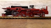
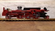
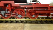
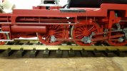
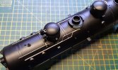
Piko BR 64 Review and Upgrade

Zerogee

Clencher's Bogleman
25 Oct 2009
17,351
1,723
North Essex
Best answers
0
Country flag
You know what, I used to think I was an OK modeler :oops::oops::oops::oops:

I think that many (most?) of us are "looks OK at normal running distances in the garden, so it'll do" style modellers.... ;)

Seriously, I'm in awe of this thread - and fascinated to see the end result - one of the most amazing aspects is that Peter isn't just super-detailing the model, but also making sure that it will still be a fully functioning garden loco when it's all finished, rather than a display-case-queen!

Jon.
 

idlemarvel

Neither idle nor a marvel
13 Jul 2015
3,136
801
Ascot
Country
Mars
Best answers
0
Country flag
Yes these are modelling heights I have no hope of reaching but a wonder to behold.
 

Rhinochugger

Retired Oik
27 Oct 2009
36,708
4,240
North West Norfolk
Best answers
0
Country flag
Agreed, but what is also good is that the methods are clearly shown, and there are plenty of lessons that we can learn and use in our own way, even if we don't ever reach such dizzy heights
 

Zerogee

Clencher's Bogleman
25 Oct 2009
17,351
1,723
North Essex
Best answers
0
Country flag
Peter - I reckon there's a potential magazine article in this once you're finished...?
Garden Rail, maybe, or possibly CM?

Come to that, if it was translated into German, even GartenBahn Profi....

Jon.
 

musket the dog

Registered
31 Oct 2009
787
143
Leicester
nlrr.webs.com
Best answers
0
A really amazing build so far, a really inspiring example of how we can improve on what comes straight out of the box. From a technical perspective I'm in awe of how you've managed to build the brake rodding to cope with the flexi-chassis.
 
Last edited:

P A D

Registered
26 Aug 2020
42
25
70
Leeds
Best answers
0
Country flag
Many thanks for the kind words gents.

Glad you are enjoying the "build". I'm intending to add the missing front steps, brake pipes and steam heat pipes for use on an end fo end run with
screw couplings, but they will all be detachable so that it can revert back to use with the tension lock couplings on the spare trucks. You never know when it might need the flexibility in the chassis to run around tight curves.

The chassis is painted now but I can't add any images due to a glitch. I'm waiting for a reply from the administrator when it's fixed.
Cheers,
Peter
 

P A D

Registered
26 Aug 2020
42
25
70
Leeds
Best answers
0
Country flag
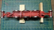
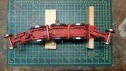
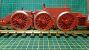
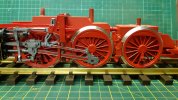
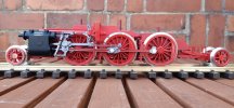
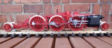
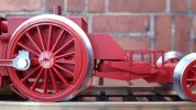
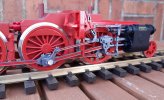
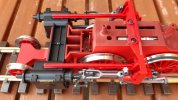
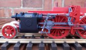
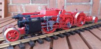
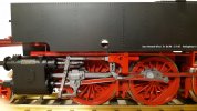
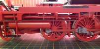
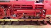
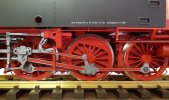
I'm still having problems loading images from my Samsung Tablet, but it seems fine on my phone. Here are some views of the painted chassis.
20200918_202941.jpg

It still bends.
20200917_201125.jpg

And on the rails
20200917_201644.jpg

Plus valve gear.
20200917_204141.jpg

I took some pictures outside on the garden table after refitting the pick ups and rods. I was loath to dismantle the mechanism at first, but once I decided to repaint the chassis it was necessary. However, it was quite straightforward and the pick ups are easily removed and refitted.
20200918_202638.jpg

The springs and pull rods are clearly visible, as are the additions to the motion bracket. I think it's a big improvement in spite of the lack of bar frame detail on the prototype, so well worth the effort.
20200918_183840.jpg

In this view you can see the chamfer on the equalizing beam to clear the rear most sand pipe. For the chassis and trucks I made a matter version of RAL 3000 using a mix of gloss and matt Tamiya acrylics.
20200918_184013.jpg

The added parts on the cylinders have now been painted black and the "I" beams have had a second coat of red. I intend to add the cylinder drain pipes, but not the operating rods as I did on the BR 86.
20200918_183757.jpg

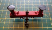
Here's an overhead view of the front end showing the location of the I beams.
20200918_184044.jpg

And a closer view of the left hand cylinder and valve gear.
20200918_184114.jpg

Here's the right hand side. The crank pin nuts have had the chemical blacking rubbed down in preparation for priming with cellulose grey. They will then be painted with metalcote steel. It's a shame Piko couldn't come up with something better for these fastenings.
20200918_183757.jpg

I'm leaving the chassis for now and will move on to the bodywork
20200918_183924.jpg

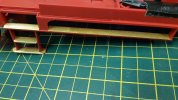
The first thing I've done is to add some etched brass chequered plate to the steps under the cab. Piko have done a reasonable representation of the grips on all the other footsteps, but for some reason left the cab steps smooth.
20200918_202511.jpg

Cheers,
Peter
 
  • Like
Reactions: 1 user

P A D

Registered
26 Aug 2020
42
25
70
Leeds
Best answers
0
Country flag
The lighting conduit and junction boxes have been added under the left hand tank, from 0.8 mm brass rod and 80 thou plasticard cut 4 x 3mm to match the moulded ones on the bunker. The missing support ahead of the rear junction box has been added from waste brass fret.
20200919_212451.jpg

On the right hand side, the piping from the air tank between the middle drivers (not modelled) and the gizmo by the middle drivers have been added from 1.0 mm brass wire, with thr gizmo made from plastic tubing and rod.

20200919_212350.jpg

Here's a closer view of the left side. All the added parts under the tanks have been primed and had a brush coat of Red. The chequered plate on the steps is primed and will be painted black.
20200919_212504.jpg

And a closer view of the left hand additions. I've also primed the crank pin nuts ready for top coating with metalcote steel.
20200919_212404.jpg

The conduit continues under the upper foot plate and around to a junction box on the footplate support. It's already drilled to accept further piping when the lower front foot plate is back in place.
20200919_212542.jpg

With one of the tanks in place, you can see the value of drilling out the inspection hole. The top of the expansion link can now be seen and should be visible when the loco is in motion.
20200919_212739.jpg

Cheers,
Peter
 

P A D

Registered
26 Aug 2020
42
25
70
Leeds
Best answers
0
Country flag
Today I airbrushed all the red parts on the body base and brush painted the chequer plates in black on the steps. I also added the step support on the right side, that I overlooked yesterday. 20200920_183131.jpg

The air tanks and balance pipes detach as a unit, so they were sprayed separately and then refitted after the black brush work on the steps was done.
20200920_170007.jpg

To give an impression of the small air tank above the middle driver, I painted the upper chassis keeper plate in black and then added a disc of plasticard painted red. If I'd thought about it earlier, the black aught to run about a quarter of an inch lower down, as that would be the height of the bar frames on the real thing. However, I'm not taking the mechanism apart again.
20200920_183310.jpg

Moving on to the lower footlplate at the front, I removed the oil boxes so that they could be drilled to add the feed pipes from copper wire. I've refitted them further forward where most of the illustrations I've seen show them.
20200920_200110.jpg

Here's an overall view of chassis showing the state of play so far. The front frame and footplate needs to be airbrushed in red and then I can start reassembling the front end.20200920_202814.jpg

Cheers,
Peter
 
  • Like
Reactions: 1 users

P A D

Registered
26 Aug 2020
42
25
70
Leeds
Best answers
0
Country flag
Today I made a start on the bufferbeams. The intention was to remove and replace the moulded brake pipe handles, as well as the moulded "draw hook". The hook will be replaced by a screw type coupling from Garden Railways Ltd. The brake pipes will be added from wire and will be a push fit so that they may be removed if required. At the front, the footsteps and steam heating pipe will be made on a brass plate and fixed via the buffer beam screws, again so they are detachable. At the rear I will only make a smaller plate for the steam pipe, with the brake pipes being push fits in their locations as at the front.

However, it struck me that the buffer stocks were way too short as illustrated by this image downloaded from t'internet. It's also interesting as it shows nine spoke pony wheels at the front, with seven spokes at the back. There are illustrations that show these the other way around, or 7 spokes plus a disc wheel, or nine spokes and a disc wheel. The gizmo I added over the middle driving wheel can also be seen as can the "I" section virder running from cylinder to motion bracket. Note also the the electrical junction box on the motion bracket and the one further forward linked by the conduit. As far as I can tell, this equipment is only on the right side on locos with the below tank inspection lights. You can see the forward light just ahead of the expansion link. Note also the welded end plate to the preheater, as opposed to the bolted on type on 64 491. This loco has additional brakes on the pony trucks and the open grill type footsteps at the front with a wider step at the bottom. Some locos also had caliper style brakes similar to Bulleid pacifics on the driving wheels. Just like BR Standard locomotive, these German "standard" locomotive whilst having many interchangeable parts between different classes, also showed a lot of variations within individual types. The forward position of the oil boxes on the top edge of the frame above the front pony wheel, as mentioned in my previous post, can also be seen.
original BR 64.JPG

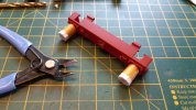
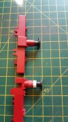
In 1:25 scale the difference in buffer length works out at about 5 mm. Therefore I decided to lengthen them using 2 layers of 80 thou plasticard, which increases them by just over 4 mm. I laminated two 12 mm lengths with super glue and when cured, drilled 4 x 5 mm holes suitably spaced and then cut into approximate squares. Using the drill to align them, the laminates were then super glued to the buffer stock ends. The dimensions and alignment of the laminate is not critical, only the alignment of the holes. You can see the replacement handles on the brake valves added from 0.8 mm brass wire, filled flat.
20200921_135129(0).jpg

Then as much as possible of the excess was snipped off with side cutters and remainder filed and sanded to shape.
20200921_135544.jpg

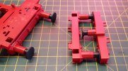
This comparison of the lengthened stock, verses an original (in this case on the central buffer supplied with the model for narrow gauge operation) shows the improvement.
20200921_154527.jpg

The white extensions on the buffer stocks were given a couple of brush coat of red to "prime" them and were then airbrushed to level up the shade with the rest of the parts. Whilst I was at it the front frame extension was also sprayed. Again, I show a comparison with an original buffer stock.
20200921_184343.jpg

With these sub sections sprayed up, I was then a le to start reassembling the chassis. Here's a view of the front end. The small step on the ladder between the lower and upper footplate has been painted black with Humbrol satin black 85. This better matches the sheen on the Piko black, so I will redo the step plates at the cab end in this colour. The semi gloss black from Tamiya is too glossy. Where necessary, parts that were only push fit (the ladder for example) will be super glue to ensure a close and more secure fit. The base for the coupling hook has been drilled 1.0 mm but will need elongating to suit the hook after I receive it. (on order)
20200921_184215.jpg

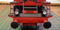
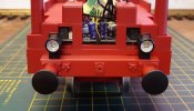
And the rear end. For some reason, German locos have a flat head buffer on the left (looking head on front and rear) and I will replicate that also. The buffer heads are just a tight push fit.20200921_184128.jpg

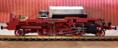
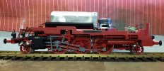
And a couple of broadside views fo finish the post.
20200921_184255.jpg

The die cast weight has now been replaced and boy does it give you a hernia every time you pick it up. The whole model weighs in at over 7lb, which is more than double the heaviest 0 Gauge model I have ever owned ( the Duke of Gloucester 4-6-2 shown earlier). I think you garden railway boys (and girls) must all be body builders!
20200921_184235.jpg

I still have to do the cylinder drain cocks and the front footsteps and steam heat pipes, but I think I'll leave that for now and move onto the body detailing.

Cheers,
Peter
 
Last edited:

P A D

Registered
26 Aug 2020
42
25
70
Leeds
Best answers
0
Country flag
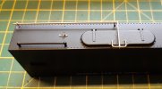
Moving on to the tanks I've replaced the moulded lifting hooks, added rivets to the base plates and the remote opening mechanism for the lids that allowed the crew to open them from inside the cab.
20200922_191203.jpg

Here's the pair completed before priming and painting black.
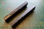
20200922_173902.jpg

And after painting. I've also added some etched chequer plate to the steps which again were plain as it comes from Piko.
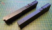
20200922_191047.jpg

The lifting hooks on the bunker have also been replaced and rivets added to the hook bases.
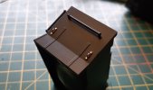
20200923_172152.jpg

While the bunker is off the model I thought it made sense to add the coal. First I taped over the slot on the top plate to prevent the PVA dropping through.
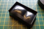
20200923_172127.jpg

To keep the coal from overlapping the open bunker edge and preventing the bunker locating correctly against the cab rear, I taped a piece of plasticard over the gap. PVA was then spread over the base and the coal added. When the glue had partially set, the plastic card was removed.
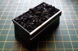
20200923_170814.jpg

As far as I know, the platform on the bunker rear was planked, so I scribed some grooves using a spring bow compass. I'm not sure if 5 planks is correct, but I recall seeing an image somewhere that suggest that it is. I gave the planks a scrub with a wire brush to suggest the grain. We'll see if it worked after painting and weathering.
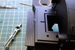
20200923_172437.jpg

The lifting hooks on the roof were also replaced and here's why. The moulding is neither a hook or a loop so off it came.
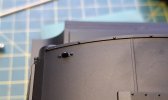
20200923_172301.jpg

Here the hooks are being added from copper wire. One down, three to go
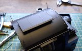
20200923_172216.jpg

Then these arrived in the post, so I went off on a tangent and took the buffer beams off. They're not cheap but they are very nice.
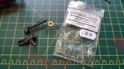
20200923_132253.jpg

They come with a spit pin to keep the springs in place, but I prefer to use a short length of brass rod bent in the middle. It works just as well and is easier to get in and take out.
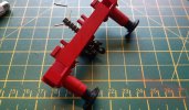
20200923_170738.jpg

Here's the front beam after refitting. To be honest, the coupling looks a little large as it never struck me when I ordered them, but they are probably to 1:22.5 scale not 1:25. That said I'm happy with them.
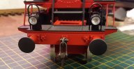
20200923_170637.jpg

And the rear beam. You can see here that the right hand buffer head has been rubbed flat and the left one rubbed to a dome as per German railway practice.
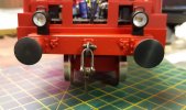
20200923_170606.jpg

Here the bunker and cab have been placed on the model for the photo. The planks have been painted and had further scraping, but have yet to be weathered. There are one or two gaps in the coal load, but those will be filled with more lumps when the bunker is screwed back to the cab.
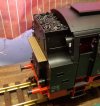
20200923_170153.jpg

Here's a point regarding Piko's quality control. The model was bought second hand, but came to me in Pristine condition from the original owner. Having almost completely dismantled it I can say that the assembly in the Piko factory was first class. However, working on the cab today I noted that all four cinder guards on the open cab windows were incorrectly fitted. Below are views of both sides after. First the left side after thr one nearest the camera had been removed and refitted. Notice the gap at the bottom of the rear guard.
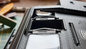
20200923_172103.jpg

And on the right hand side, you can see both guards are lifting at the bottom. No big deal, but this glazing is quite brittle so it's best not to have to mess about with it. One black mark to Mr. Piko. It's a good job he wasn't in the cab, or he'd have been given a right bollocking!
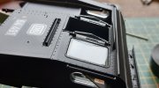
20200923_172041.jpg

And to finish off, a view from ground level.
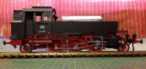
20200923_220826.jpg
Cheers,
Peter Dunne
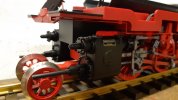
 
Last edited:

Zerogee

Clencher's Bogleman
25 Oct 2009
17,351
1,723
North Essex
Best answers
0
Country flag
Those Regner couplings really look the part, Peter....

Jon.
 

P A D

Registered
26 Aug 2020
42
25
70
Leeds
Best answers
0
Country flag
Hi Jon,
They certainly do. I've been trying to find a casting for the steam heating coupling, but no luck so far. Do you know if anyone supplies them for G?
I've been searching for spur g and spur II heizkupplungen. I can find them for guage 1 as I used them on the BR 86, but I think they will be too small at 1:32 and look a bit emaciated. At the minute, it's looking like I'll have scratch them up in brass.

I see I left a couple of thumb nails in the last post (one a duplicate), so I've deleted them to tidy up. This one I overlooked and is to show the domed and flat buffer heads. Not sure why they are like that - something to do with locking on curves???
Cheers,
Peter
20200923_170713.jpg
 

P A D

Registered
26 Aug 2020
42
25
70
Leeds
Best answers
0
Country flag
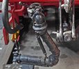
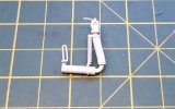
Today I decided to have a crack at making the heizkupplungen. This is the real thing on a BR 86, which I've used as a base. There was some variation with the isolation valve so I'm not trying to make an exact copy just something that looks the part.
br86x543.jpg

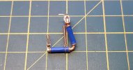
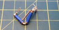
I don't have my soldering station as it's at my brother's where my actual workbench is. I'm slumming in the garage with limited tools and raw materials, so I thought I'd see what I could with what I have to hand. Here's what I made from various diameter copper wires, brass strip, plastic tube brass wire and the insulation from a short length of 13 amp cable.
20200924_181926.jpg

It's not perfect, but I think it will pass muster.
20200924_181857.jpg

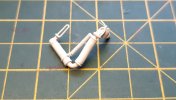
And after a waft of primer.
20200924_181736.jpg

20200924_181802.jpg

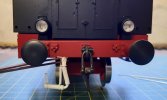
This gives an idea of how it will look on the model. It may be a touch on the small side but I don't have a drawing and am having to estimate the size from photos. It could be that the 1:22.5 scale coupling is making the heating coupling look small??? The cab and bunker are not screwed in place and I see that I haven't seated them properly.
20200924_181826.jpg

Having made one now, hopefully the second one will be quicker.

Cheers,
Peter
 

Flying15

Registered
12 May 2015
325
307
London
Best answers
0
Country flag
Not sure if this is that helpful but Walsall Engineering do make castings for hoses but they are intended for gauge 1 models
I don’t think I’ve seen anything off the shelf for G scale or Gauge 3 models
I’ve used bits canabalised from discarded LGB bodies, but I’m not sure they are up to your standards of accuracy and precision
Great modelling
Chris
 

P A D

Registered
26 Aug 2020
42
25
70
Leeds
Best answers
0
Country flag
Hi Chris,
Thanks for that. Our posts have crossed in the aether and as you can see I've had a crack at scratching them up.
Cheers,
Peter
 

P A D

Registered
26 Aug 2020
42
25
70
Leeds
Best answers
0
Country flag
Today I made the second steam heating coupling. I thought it might be of interest to show how I did it.
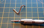
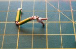
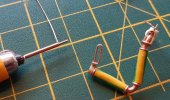
First the basic shape is bent from 1.8mm copper wire and trimmed to size at the bottom, but with an extension at the top to allow for location into a mounting hole on the loco. For the flanges I used 0.8mm copper wire for the 4 smaller ones and 1.0mm for the large one. Taking a length of 1.8mm wire mounted in the pin vice, the thinner wire is then coiled around it by holding one end over the chuck and rotating the pin vice.
20200925_171212.jpg

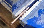
After trimming the excess both wires are clamped in the vice and the thinner wire sawed through with a razor saw.
20200925_171045.jpg

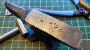
This gives a number of rings which after removing have the ends lined up by tapping with a small hammer on a hard surface. The gap between the ends is closed by squeezing in a pair of pliers.
20200925_112149.jpg

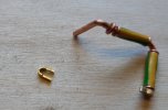
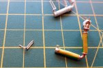
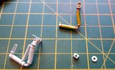
Two lengths of the 13 amp wire insulation are then cut to 12 mm. The upper one is mounted on the 1.8 mm copper wire from the bottom end and push around the bend into position. Heating the insulation softens it and makes it easy to push onto the wire. The upper and lower flanges are then pushed up tight to the insulation and super glued in place. Pushing the flanges on causes them to splay leaving a gap, this is positioned at the rear out of sight before gluing. The inner flange on the lower section is then mounted, followed buy the insulation and the outer flange. Again the flanges are glued with the gaps to the rear. The upper larger flange is then added leaving a gap to the top small flange. The clamp at the bottom end is made by wrapping a length of brass strip around a separate piece of 1.8mm wire, squeezed tight and then located on the coupling and glued in place. After trimming to length with side cutters, a hole is drilled for mounting the stowage loop.
20200925_165156.jpg

The upper clamp seen above is made from brass strip, folded and trimmed to length and a hole drilled through the bend. Then comes the tricky bit of drilling the mounting hole in the bend at the top of the coupling. Once done, the clamp is located with a length 0.8mm copper wire and glued in place. The stowage loop was folded up from 0.6mm copper wire.
20200925_165025.jpg


The valve at the top is made from a short length of styrene tube, drilled through 1.8mm to fit on the top of the coupling. The flange was made from a disc of 20 tho plasticard made with a leather punch and drilled 1.8mm.
20200925_165129.jpg

The hole in the top of the tube is filled with 1.8mm copper wire, trimmed and filed flush, and a 0.6mm hole drilled for the handle pin.
20200925_165051.jpg

Here, the valve handle, made from brass strip, has been fitted and the return spring between the "two" coupling sections has been made from 0.4mm copper wire, coiled around 0.8mm brass rod.
20200925_164915.jpg

After trimming the spring, leaving about 10 mm of uncoiled wire extending at each end, it is attached to the coupling top and bottom by wrapping the excess wire around, trimming and glueing in place. To add a bit of strength, the length of brass rod is left inside the coil. In the second one I positioned the bottom of the spring closer to the bend, which better matches the prototype. I then adjusted the spring on the first one to the same position. As can be seen, I tried to represent the perforations in the lower coupling, but the holes, whether drilled or punched with a point, simply close up again in the soft insulation.
20200925_164812.jpg

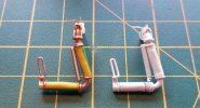
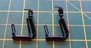
After a waft of primer they were given a coat of black. The holes in the first one have filled in with paint so the pair match reasonably well. Not that it matters too much as when they are mounted, you won't be able to see both at the same time. If anything, the gap between the upper flanges on the second one is too large and I may saw through, file to remove excess metal, then drill each part and pin/glue together. Obviously a more robust fitting could be made by using an all metal construction and soldering, but as I mentioned earlier, I'm having to make do. The black is a bit shiny but weathering will take card of that.
20200925_164746.jpg

Cheers,
Peter
 
  • Like
Reactions: 1 users

dunnyrail

DOGS, Garden Railways, Steam Trains, Jive Dancing,
Staff member
GSC Moderator
25 Oct 2009
26,164
4,989
75
St.Neots Cambridgeshire UK
Best answers
0
Country flag
Like you I enjoy fiddling around with sundry bits of thin wire and mains wire to make up details, but you have given me some new ideas for my next job and perhaps to enhance previous ones. Thanks for the inspiration..
 

P A D

Registered
26 Aug 2020
42
25
70
Leeds
Best answers
0
Country flag
Thanks dunnyrail. Glad you are finding it useful.

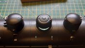
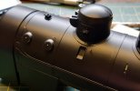
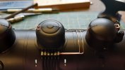
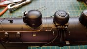
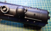
I decided to move onto the boiler for a bit and made a start on adding some of the missing details and removing and replacing some of the moulded ones. First the lid details on the steam and sand domes. I scraped off the snecks and stoppers and replaced them with items made from 0.6mm copper wire, flattened as appropriate.
20200926_200025.jpg

Next, the missing air lines from the sanding controls in the cab to the sand guns. As I don't want to have to do a major respray on the black parts, I could not use super glue to fix the airlines, so instead I used small loops of 0.4mm copper wire located in holes drilled in the boiler cladding. Here are the loops ready for fitting.
20200926_135313.jpg

After marking the position and drilling the holes, the loops were pushed part way home.
20200926_195953.jpg

Two lengths of 0.6mm copper wire were straightened by rolling between a length of wood and the bench surface and then super glued together along about half their length. This is just to keep them together for inserting into the loops. Once inserted and lined up, the loops are pushed home tight and then spread on the inside to retain them. After the third loop, the line separate to form a parrallelogram before running behind the sand guns on the dome (removed for now). The ends of the wires were inserted into holes drilled the dome ring out of sight and glued.

20200926_195907.jpg

Unlike the BR 86 which has two sets of air lines running either side of the domes, the ones on the left side of the 64 branch off from the ones on the right, loop over the boiler top and then forward to the sand guns. To make a representation of the pipe unions I flattened and filed the ends of the wire, formed a curve around a 0.6mm drill shank, then looped and glued them over the right hand pipes. Not perfect but they pass muster. With the sand valve moulding in place, the ends of the lines, again glued into holes, are hidden.
20200926_184944.jpg

20200926_161006.jpg

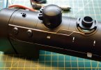
On the safety valves, many German locos have a lever which is linked to controls in the cab, which allows the engine men to blow of steam. The Piko
safety valves have the levers, but not the links to the cab, so I set about adding these. However, the valves first need modifying to allow them to be rotated through 90 degrees so that the levers are to the side not the rear as they come. The locating lug is an oblong shape and needs to be filed square and shortened to about 1.5mm to allow the valves to be turned and reinserted in the location. Here they are after modifying. They were only push fit but I super glued them after first drilling a 0.6mm hole in the bottom of the lever to allow the linkage to the cab to be added.
20200926_184911.jpg


The operating lever was made from 1mm brass rod flattened and bent at the end and drilled 0.6mm to accept the link from the safety valve lever. The stanchion was made from brass strip, drilled 0.8mm in the base and secured with brass rivets and super glue.
20200926_184728.jpg

Here they are completed. The control rods will be trimmed later to butt up against the cab front.
20200926_184815.jpg

The sand guns are missing the feed pipes from the airlines, so to fit these the unions need drilling out. The copper wire I'm using is 0.45mm, but for easy insertion, I drilled 0.5mm.
20200926_184837.jpg

I had to leave it then, but the wire will be looped under the guns between the sand pipes and glued to the underside of the sand gun mount to give the impression that they are connected to the air lines. That's the plan anyway.
20200926_184646.jpg

Cheers,
Peter
 

Zerogee

Clencher's Bogleman
25 Oct 2009
17,351
1,723
North Essex
Best answers
0
Country flag
Getting more amazing with every new post.... :)

Jon.