Piko BR 64 Review and Upgrade

P A D

Registered
26 Aug 2020
42
25
70
Leeds
Best answers
0
Country flag
Hello everyone,
My name is Peter and I'm a new member and convert to G Scale. I've been an O gauge kit builder for over 30 years building loco kits mainly for my brother, but in recent years more for myself. Here are some examples of my work.
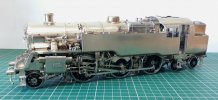
BR Standatd 4MT built from the Modern Outline Kit.
20180929_182316.jpg

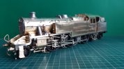
LMS 4P built from the David Andrew's kit.
20190613_173446.jpg

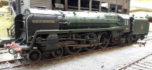
BR 8P Duke of Gloucester built and painted by me from the Seven Models kit.
post-13414-0-98925600-1493643445.jpg

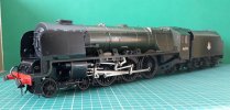
LMS Princess Coronation - Dutchess of Sutherland, built by md and professionally painted by Warren Hayward .
20190211_183620.jpg

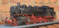
During the lockdown period and until recently, I've been building a plastic display model of the German Baureihe 86 from the Trumpeter Models kit. This was something completely new to me in terms of prototype, railway and the medium.
20200824_132851.jpg

Building this latter kit has sparked my interest in German locomotives and prompted an internet search of what was available in terms of kits and RTR in the larger scales. In terms of kits there is zilch, but lots of RTR in gauge 0 and gauge 1, albeit at very high cost. During my searching, I discovered the Piko G gauge BR64, which I took a fancy to. Searches for reviews led me to G Scale Central where although I didn't find a review, I did find one for sale at a good price! That's the context of how I got here so on with the review.

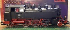
The model as purchased is in mint condition and came in the original box, with the additional detail parts still in the bag. Here's what it looks like out of the box.
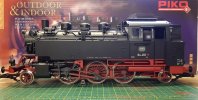
20200902_192129.jpg

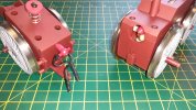
And the other side. One of the first things that struck me was the colour of the wheels and the bare metal rims, so I quickly primed and repainted one of the front ponywheels to see how it would look. A big improvement to my eye.
20200902_192202.jpg

I'm going to end it here for now and continue later, as I inadvertently opened the preview and can't close it and it's driving me mad having the post duplicated on the screen. I don't see the need for a preview when you can type and add images as you go and can see everything.

Cheers,
Peter
 
Last edited:
  • Like
  • Love
Reactions: 4 users

idlemarvel

Neither idle nor a marvel
13 Jul 2015
3,136
801
Ascot
Country
Mars
Best answers
0
Country flag
Excellent kit building! Welcome to g scale. Plenty of scratch-building and kit-bashing opportunities here.
 

dunnyrail

DOGS, Garden Railways, Steam Trains, Jive Dancing,
Staff member
GSC Moderator
25 Oct 2009
26,160
4,986
75
St.Neots Cambridgeshire UK
Best answers
0
Country flag
Welcome to the forum some nice 0 gauge work. The 64 and most of the recent Piko Models are quite good if slightly off scale when you compare measurements to track gauge, a common phenomenon in G scale by sundry Mfg’s LGB (Marklin) included. My mind goes back to Triang TT gauge at 3mm to the foot on 12mm Track Gauge. Looks OK from the side but the front view is well off. Your 64 is a later one with plated wheels though very shiny will ensure good eunning with regards to pick up prowess. Certainly it will benefit from some changes to in-service condition, depending on what you are going to do with it removal of the LGB type couplings, screw couplings and sundry pipes at the front for services to vehicles will lift it considerably. Look forward to a pic of what you do with it.
 

JimmyB

Now retired - trains and fishing
23 Feb 2018
6,944
921
69
Weston-super-Mare
www.tumble-down-falls.co.uk
Best answers
0
Country flag
Hello everyone,
My name is Peter and I'm a new member and convert to G Scale.

I'm going to end it here for now and continue later, as I inadvertently opened the preview and cant close it and it's driving me mad having the post duplicated on the screen. I see the need for a preview when you can type and add images as you go and can see everything.

Cheers,
Peter

Peter, welcome to the forum, when you hit "Preview" the Preview screen is at the bottom of "your" box, and your original is in a box above the Preview which you can then continue to edit. I have to admit not what I am use to on some forums, but it does work, I currently have the Preview of this message (to check it worked) then continued to edit.
 

PhilP

G Scale, 7/8th's, Electronics
5 Jun 2013
33,558
3,521
Nottingham
Best answers
0
Country flag
Hello Peter,
Welcome to the Forum..
Some lovely models, and fine workmanship there. :)
 

P A D

Registered
26 Aug 2020
42
25
70
Leeds
Best answers
0
Country flag
Thanks to all for the welcome and positive comments.

I am fully aware of the scale discrepancies here and there on the body plus the compromises made on the chassis to enable the model to negotiate 600mm curves. None of that concerns me as the important thing to me is that it looks the part when sat on the rails, ignoring of course the too narrow track gauge. In 0 gauge the narrow track doesn't bother me and I have never had any inclinations towards Scale 7. My reason for purchasing the model is to be able to run something in the garden bigger than 7mm scale and German based. The bonus with this model, is that it came ready fitted with a sound chip and smoke unit, which is something I've never considered in 0 gauge.

Dunnyrail mentioned the model being a later one with plated wheels. It's a actually an early one purchased in 2014, but I don't know about plating on the tyres. They are stainless steel according to the website. Another contributor in a past post, questioned whether the inspection lights under tanks were ever fitted on BR 64s. From what I've discovered, they were fitted to a few and I've seen photos on the internet to confirm that. Whether they were on 64 491 is doubtful, but they can be left switched off and further hidden by pushing the bulbs up into the locations. By the way, pretty much everything by way of detailing is push fit, which is a boon when it come to dismantling. All the various sub assembles are screwed though, with a limited number of parts glued. I'll come back to that later.

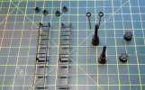
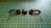
After taking it out of the box my first impression was very positive. The model shows a very high level of detail on the body including separate details to be added as desired by the owner. These are the extra parts.
20200902_192303.jpg
A pair of buffer beams with a central buffer are included for running with narrow gauge stock.

And a quick walk around. First the rear dome with safety valves and whistle.

The left hand valve gear is nicely rendered, albeit in plastic. The rivet pins will need some work to fill the holes and make them look more realistic. The red colour is the rod fluting is a sticker ot paint, but at least it's more or less the right colour, unlike the wheels.
20200902_185540.jpg
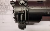
The water pump and preheater detail on the left hand side.
20200902_185814.jpg
The right hand side of the preheater with the compressor below. Also note the piston tail rod, upper platform grab rails and the hand wheel on the forward dome have been added
20200905_162430.jpg
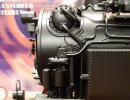
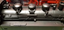
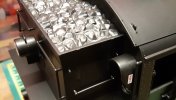
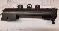
This image shows the central sand box and piping, the steam manifold in front of the cab, the two steam domes, bell and chimney which is fitted with the smoke generator. Nice detail on the tank top although the moulded lifting hook will be replaced with something more realistic. The filler lid is missing the remote operating lever from the cab as is the whistle and the sand guns don't have the air feed pipes either. The circular cover on the tank front end was to fill the hole left after a grease separator whi h removed greass from the condensate, was removed after ig was decided ig was no longer required. I don't thing 64 491 ever had this fitted so would not have the round plate, but I will live wit that.
20200902_190044.jpg
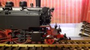
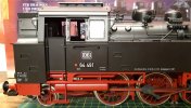
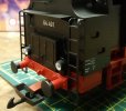
Here's a view of the cab area showing the nicely rendered number plates etc. The odd colour of the wheels compared to the other red areas of the chassis shows up well.
20200902_191343.jpg
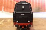
And a view of the bunker with the ladders fitted.
20200906_223945.jpg

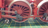
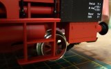
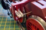
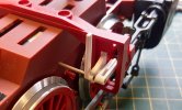
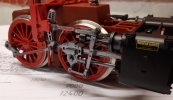
This is a view of the return crank with the screw removed. This, the big end of the connecting rod and the bosses on the coupling rods all have nicely rendered mouldings of the oil pot lids. The brake hangers are also very nice with bothe the clip at the bottom of the brake block and the adjuster on the hanger at the top. The pick up shoe between the front and middle drives is clearly visible here, and coming from O gauge, it's something (along with the tension lock couplings), that I find to be a bit of an eysore. As you can see, I've already centre popped the wheel boss ut more on that later.
20200906_223117.jpg

Here's an oblique view oc thd rear end showing the coupling on an extension of the pony truck.
20200902_185056.jpg

This view shows the cutouts in the tool box and rear step to accomodate the swing of the pony truck on tight curves.
20200902_185435.jpg

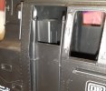
All the hand rails are separately added items apart from those in the cab entrance which are moulded in place so don't have a round profile. I may leave these as they are not so obvious to the naked eye from normal viewing distances but we'll see. I'm not sure if the locker in the cab was there in service or is based on later preservation mods.
20200902_190943.jpg

The moulded "coal" which will definitely be replaced with the real stuff.
20200902_191233.jpg

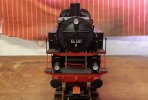
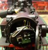
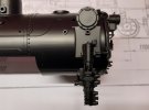
And finally for this post, some views of the front end. The top fastener to the left of the upper lamp rotates to allow the smokebox door to open.
20200906_223737.jpg

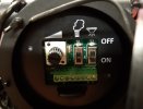
Revealing the switches for the smoke unit, inspection lamps under the tanks and the volume control for the sound.
20200902_191717.jpg

The switch board slides out to reveal other electrical stuff behind a d the chimney can be twisted via a bayonet fixing to remove the smoke unit.
20200902_191639.jpg

For now I only have an analogue controller and so far have only tested the loco with clips to the wiper shoes propped up on the pony wheels. The various sounds from the Massoth unit are very good and I'm sure will be even better with DCC, when the choice and time of sound can be chosen. Control wise it runs very smoothly off the rails, but since obtaining a couple of lengths of straight track, I've not been able to test it as it has been dismantled for painting and further detail additions. Directional illumination of the lamps, stainless steel tires with ball bearings and plunger pick up on all the driving axles, along with a Buhler 7 pole motor are all part of the spec. More annon.
Cheers,
Peter
 
Last edited:
  • Like
Reactions: 1 users

idlemarvel

Neither idle nor a marvel
13 Jul 2015
3,136
801
Ascot
Country
Mars
Best answers
0
Country flag
Nice review, thanks.
Ref your comment about pick-up shoes, I tend to remove them from my locos for aesthetic reasons. On this model you have plenty of wheels and long wheel base so you hardly need them, and if you find you do there is plenty of room for some stay-alive capacitors.
 

Madman

Registered
25 Oct 2009
17,132
2,949
Pennsylvania, USA
Best answers
0
Country flag
Welcome aboard Peter. I must commend you on the talent you possess.
 

P A D

Registered
26 Aug 2020
42
25
70
Leeds
Best answers
0
Country flag
Thank you Dave and Dan.

Dave, my intention is to fit some wiper pick ups to the trucks made from phosphor bronze wire.

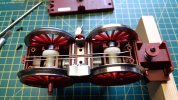
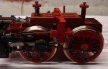
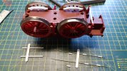
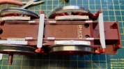
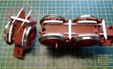
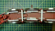
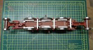
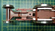
Continuing with the review, here's a view with the loco inverted. The large amount of swing in the trucks can be seen, although adding the piston tail rods severely limits the front one. The split coupling rods with elongated holes in the rear ones facilitates the negotiation of 600 mm curves in conjunction with the pivoting front section and the articulated rear. The motor is in the front section and drives both axles and also drives the rear wheels via a cardan shaft. Therefore, the rods are purely cosmetic. Note the traction tires on the middle drivers, the lack of driving wheel spring detail, brake crossbeams and pull rods, cylinder drain cocks and relief valves, plus no guard irons which would hinder the swing of the trucks.


Before commencing with the addition of the missing details, I decided to dismantle the model as far as possible into various sub sections, but leaving and much oc ghd electrics as possible in there locations with the minimum removal of wiring. Any wires that were removed, were photographed in-situe to ensure the correct refitting.

I did not receive a manual with the model, but this may be down loaded as a pdf file from the Piko website. It explains in detail via sequenced drawings how to do it. I have it down loaded but the file is too big to attach. Here's a link to the web page.

Any way, first off were the trucks.
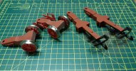
20200906_115307.jpg

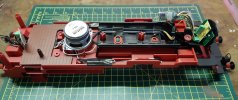
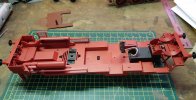
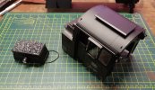
After removal of 4 screws, the cab/bunker, boiler and tanks may be removed. This is the lower part of the body after removal of the upper works. This allows access to the three retaining screws for the chassis, located on the raised lugs , the third one being under the speaker which needs removing to gain access. At this stage the wiring from the smoke generator and rear lamps had been unscrewed from their locations on the circuit boards. The cab floor can also be lifted out. This also has the podium on which Mr. Piko sits, but sadly, the previous owner was too attached to him to include him in the sale. Sorry Zerogee! :)
20200906_222846.jpg

This is the underside of the the lower body without the chassis. The wired plug has been detached from the pick ups in the chassis. You can see the under tank LEDs for illuminating the motion etc., but if not required they can be pushed upwards into the locations without removal.
20200906_222803.jpg

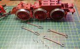
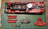
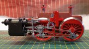
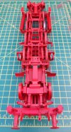
Here's the chassis after removal of the valve gear anc cylinders. The brake shoes are a nice rendition of the dual brake block fitted hangers. Below are the coupling rods and and retaining screws.
20200906_222948.jpg

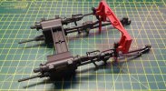
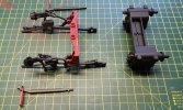
And the valve gear and cylinders. This unit may be further brocken down as I will show later.
20200906_222909.jpg

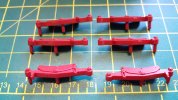
The brake hangers and shoes can also be removed from push fittings on the chassis.
20200906_151409.jpg

Here's the chassis with the universal joint removed.
20200906_151527.jpg

The cab, boiler and tanks are four separate sub sections and the upper part of the bunker detaches from the main part.
20200906_222653.jpg

This was an unexpected bonus. The dummy coal load separates from the bunker, so the laborious task of drilling the corners then sawing out the middle, filing to tidy up, then adding a base for real coal will not have to be needed. Well done Mr. Piko!
20200906_222622.jpg

Here's a view of the tanks. The one on the left shows how they come with the inspection hole having a backing plate. This seems to be the norm on many German RTR prototypes which had these holes, so the one on the right has had the backing drilled through. The other has since been drilled out as well.
20200906_195208.jpg

I overlooked to take a picture of the boiler on it's own so that will follow later. However I've removed all the push fit details to avoid any damage while I'm working on it. Here's the sand box and pipes.
20200906_120127.jpg

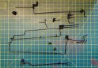
And all the separately fitted pipes and valves etc.
20200906_223526.jpg

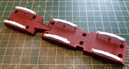
This is how the front and rear chassis sections separate at the pivot. The wires have brass fitting ag each end allowing easy removal from both sections.
20200907_101105.jpg

Just for interest, here's the keeper plate removed from the front motor section revealing the bus bars for the pick ups and the ball bearings on the driving axles.
20200908_095655.jpg

The lower body sub section can be further broken down by removing the front platform, steps, buffer beams and air tanks under the cab.
20200908_200811.jpg

And the valve gear and cylinders can be separated also.
20200908_200653.jpg

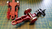
It is unlikely that the garden management will authorise the building of a circuit, so I'll have to make do with an end to end down the longest wall with possibly a bend providing further running along the short end wall. With that in mind I won't require the negotiation of tight curves so I'm dispensing with the tension lock couplings and extensions on the trucks. However, I don't want to burn my bridges in case I wish it to run on tight curves in the future, so I've bought a couple of spare truck (no wheels or couplings) from Piko, removed the extensions and swapped the wheels over.
20200908_200603.jpg

As some of you may have spotted, I've already made a start on painting the wheels, but more of that later.

Cheers,
Peter
 

Rhinochugger

Retired Oik
27 Oct 2009
36,706
4,240
North West Norfolk
Best answers
0
Country flag
OK, now we've taken it apart :worried::worried::worried::worried:
But seriously, as someone who once built white metal 00 kits semi-professionally, I'm in awe of the 0 Gauge models :clap::clap:

And it's nice to see the enhancements on the BR64 - there's nothing like having your own model :nod::nod:
 

P A D

Registered
26 Aug 2020
42
25
70
Leeds
Best answers
0
Country flag
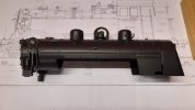
So just to complete the "walk around" of the model, here are some views of fhe stripped down boiler. On the left hand side it has the multiple lubricating pipes nicely moulded on the boiler cladding, running from the grease pump in the cab to their various lubricating points. Shame they are hidden behind the tank when the model is assembled.
20200911_204707.jpg

And t'other side. The lower part of the boiler is fixed to the the body base with a slot down the middle for the 2lb cast weight included to increase adhesion and pulling power no doubt.
20200911_204049.jpg

Here's a closer vies of the water pump.
20200911_204448.jpg

And the compressor.
20200911_204128.jpg

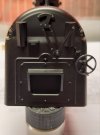
And the backhead which is very sparsely detailed. I have drawings and pictures of the prototype and on the BR 86 all the fittings were modelled, including all the handwheels and dials. I'm not going to bother with that on the 64 as most of it is not visible and it was really just a bit of a vanity project on the 86.
20200911_204011.jpg

So that concludes the review of the model as it comes, which overall is pretty good for the money, even at the current retail prices. I've checked several of the model dimentions against those of the prototype and they come out at between 1:25 to 1:28. The model on the whole is well detailed, but there is scope for quite few additions and modifications to enhance the appearance.

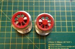
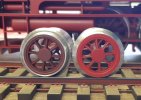
First on the list are the pony truck wheels. Outside diameter is 31.8mm so that scales out at 1:27. The BR 64s were fitted with two types of spoked wheels, one with 7 spokes and one with 9. Some were also fitted with disc wheels and all three types were 850 mm diameter. Overtime it was possible to see combinations of the three types, (7 spoke front, 9 spoke rear and vice versa and the same could occur with disc wheels). The model's wheels have 8 spokes so don't match any of the prototypes. Also, the edge of the tyre treads are not painted and there is no center boss details. The webbing on the spokes at the rim end is modelled, as it is on the driving wheels. I'm not sure if the wheels are painted or not, but the colour is way too dark for RAL3000, the official spec used by the DB. Here's the original condition on the left, with the one on the right having been painted including the rims.
20200902_162522.jpg

I think just painting the wheels and rims makes a big improvement, but I decided to add the wheel boss detail as well. Mark I on the left mark II on the right. I made a disc from 10 thou plasticard and drilled holes to represent the detail. The wheels and rims were first primed with cellulose grey primer brushed on and then received 3 brush coated of Tamiya gloss acrylic - 2 parts red to 1 part yellow.
20200903_202556.jpg

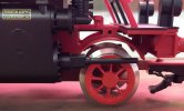
Here's how they look on the model.
20200903_202640.jpg

In this light the colour matches quite well to the Piko paint, but to the eye, you can see more of a difference, so I will repaint all the red parts, with the airbrush where possible.
20200903_202724.jpg

I've done the same thing with the driving wheels, but these are more difficult to do as I did not want to dismantle the mechanism. Here are the discs ready for glueing to the wheels. The diameter of the wheels is 57.8 mm vs 1500 mm on the prototype and they have the correct number of spokes (16).
20200906_162228.jpg

After fitting to the wheels.
20200906_165231.jpg

Primed.
20200906_222446.jpg

And painted. Painting between and behind the spokes was a real pain and I used a mask of plasticard slotted to fit over the axle, to avoid the "frames".
20200908_200514.jpg

Cheers,
Peter
 

P A D

Registered
26 Aug 2020
42
25
70
Leeds
Best answers
0
Country flag
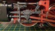
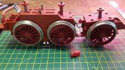
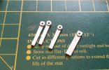
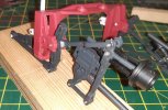
Moving on to the motion bracket, I set about making the missing lifting links, reversing lever and shafts. The lifting link were made 30 thou plastic card lamination. Here are three of the 4 almost done. After filing the 1st one to shape by trial and error, I clamped the others back to back with the 1st in the vice and used it a a template to make the others.
20200910_225916.jpg

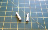
Here they are completed with an insert added to represent the back end of the radius rod.
20200910_225850.jpg

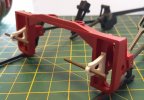
Here are the mounting brackets, also made from laminated 30 thou plasticard after super glueing to the motion bracket.
20200910_230011.jpg

And with the lifting links added on the left side
20200910_225733.jpg

On the right side the reversing lever has also been added on the inside of the support bracket.
20200910_225755.jpg

After that, I set about plugging the recesses in the valve gear rivets to improve the appearance. I made a nut from plastic for the joint between the return crank and eccentric rod.
20200911_142206.jpg

Here are some views after painting the motion bracket parts in RAL3000 and the valve gear in Humbrol metalcote steel with the fluting in RAL3000.
20200911_203601.jpg

The metalcote polishes up nicely, but will be weathered later to tone it down. The reversing rod will need to be cut down to clear the underside of the body, but as it's plastic I can do that easily with the side cutters.
20200911_203513.jpg

The motion bracket on the left hand side is painted, but I've still to do the valve gear.
20200911_203910.jpg

Cheers,
Peter
 

P A D

Registered
26 Aug 2020
42
25
70
Leeds
Best answers
0
Country flag
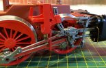
The left hand valve gear has now been fully painted.
20200913_185211.jpg

And the reversing lever has been moved inwards to clear the bottom of the tank and has been trimmed.
20200913_185536.jpg

The drain pipes from the valve chests have been added as have the cylinder relief valves. In both cases, these are fitted front and back.
20200913_185610.jpg
20200913_185341.jpg

A prominent feature of these locos are the "I" section beams running from the top of the cylinders to the motion bracket. These are omitted by Piko so I have added them from Plastruct.
20200914_154231.jpg

The driving wheel spring detail is also missing so this has been added from plastic strip, tube, brass rod and 10BA nuts and bolts. At this point only the top right spring has has the hanger bolts cut down to size.
20200915_215221.jpg

Here they are after fitting to the chassis keeper plates.
20200915_215058.jpg

Having removed the rail wiper pick ups, I bit the bullet and removed the moulded mountings on the chassis and keeper plates. I've also decided to paint the chassis sides in RAL3000, so it was necessary to remove the plunger pick ups and wheels. This was quite easy and should be no problem to refit them. The gaps in the chassis sides have been filled with plasticard. After removing the pick ups and wheels the keeper plate was refitted and all the holes taped up while the pick mounts were sawed off and cleaned up, so as to avoid getting fillings in the gears.
20200915_215329.jpg

I've made a start on the brake cross beams and pull rods which will be removable for chassis maintenance. These will only be a simple representation, as I don't see the point adding detail that won't be seen on the track.

Cheers,
Peter
 
  • Like
Reactions: 1 user
Zerogee

Clencher's Bogleman
25 Oct 2009
17,351
1,723
North Essex
Best answers
0
Country flag
This is going to look amazing, Peter - one of the best super-detailed Piko large scale models around, by the time you've finished!

Jon.
 

P A D

Registered
26 Aug 2020
42
25
70
Leeds
Best answers
0
Country flag
Many thanks Jon. I hope so.

So on to the brake gear, made from 80 thou plastic card, plastic tube and 1mm brass rod. The cross beams have short lengths of brass rod glued into the ends. These slot into holes drilled in the bottom of the brake hangers, to about half way through. As the hangers are push fit in their locations on the chassis, they can be spread out slightly to allow fitting and removal of the cross beams.
20200916_151256.jpg

Here's the front section with the beams and rods in place ready for glueing.
20200916_151455.jpg

And with the rods glued to the beams.
20200916_165623.jpg

When the rear chassis section is attached to the front one, the rods from the middle cross beam slot into the tube in the rear beam. This allows the rear section to pivot on curves.
20200916_212231.jpg

As I mentioned in the last post, the brake rigging is much simplified as I'm not too concerned with detail that can't be seen. This shows how it should be as modelled on the BR 86. The 64 set up is very similar albeit with only 3 driven axles. Both the 64 and 86 had brakes on the pony wheels on some members of the class, but I ain't going there.
20200514_182900.jpg

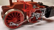
Back on the 64 the sand pipes have been added from 1.0mm brass rod. I had to add some mounting blocks from laminated 80 thou plasticard for the rear ones on the middle and rear driving wheels. This shows the full chassis with the pony trucks in place. Everything has clearance for removal and fitting, plus movement on tight curves.
20200916_214023.jpg

However, clearances are a little close between the representation of the equalising beam on the rear pony truck and rear sandpipes. It little chamfer on the outer front edges of the beams should solve it.
20200916_213934.jpg

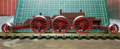
Here's a view of the chassis on the rails.
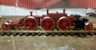
20200916_213748.jpg

All being well I'll get the chassis primed and painted in RAL3000 tomorrow.

Cheers,
Petef
 
  • Love
Reactions: 1 user

Rhinochugger

Retired Oik
27 Oct 2009
36,706
4,240
North West Norfolk
Best answers
0
Country flag
You know what, I used to think I was an OK modeler :oops::oops::oops::oops: