OPRATING PANTOGRAPHS WITH A DECODER

TONYWARD50

Tadpole sexing</br>
I AM REPLACING THE DECODER IN MY LGB RhB 27422 LOCO WITH A LOKSOUND v4 xl.
I am happy with wiring the lights, sound and motor but how do I wire a decoder to raise and lower the pantographs, as currently happens with the onboard decoder ?
Any help would be appreciated.

Regards
 
Hi, Phil.
I committed the cardinal sin and dismembered most without taking photos. However, I can tell you that each pantograph has a standard 6 pin in-line plug moulded onto the end of a flat ribbon cable. I cannot figure out why there should be 6 pins, unless some are not used, of course.
Attached is an exploded diagram with the cable to the motor circled in red.
Hope this helps.

Tony
 

Attachments

  • LGB Panto motor.jpg
    LGB Panto motor.jpg
    148.7 KB · Views: 44
Why not leave the onboard decoder in just to run the pantographs? Use the same address as the ESU then when you push the function button you get the sound from the ESU and the function from the onboard decoder.

Just a thought...

Keith
 
[quote author=Keith RhB link=topic=301291.msg351968#msg351968 date=1432790447]
Why not leave the onboard decoder in just to run the pantographs?&nbsp; Use the same address as the ESU then when you push the function button you get the sound from the ESU and the function from the onboard decoder.&nbsp;

Just a thought...

Keith

[/quote]
On the earlier models, the pantograph part used serial commands.. You could do this but it was not very good.

I used a cheapy Chinese regulator board to give 5-6V (the pantographs are `servo` type motors), and a stripboard with two DPDT relays.. fired the relays with F2 and F3 (existing LGB gubbins in the roof has limit switches).
As this was an XLS, I fired front with F2 and also triggered the panto-up sound, and the rear with F3 and triggered the panto down sound..

DSC00597-1.jpg

This shows the regulator and relay board (minus relays, they go where the dots are!).

DSC00618-1.jpg

This shows the connections to the 6-ways for the pantographs.. I hot-glued the cabin headlight connectors to the panto connectors, and wired them using pins from Maplin..

DSC00623-1.jpg

Overall view showing (in my case) XLS, and other wiring.. I did not have any of the original boards, so had to `invent` a way of driving the flashy-lights on the instrument panels.. Lots of reversing LED`s and palying with the CV settings for this!

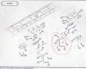
I will sort out a couple of diagrams for you for the 6-way connectors. Basically, you put your fixed volts on two pins for `up` and two others for `down`..
I will sort this out this evening for you.

PhilP.
 
Thanks, we are getting there !
I did not use the original boards as there were 3 - one decoder, one auxiliary unit and one sound board, all fed by various cables and inter-connected.
I did try using the existing boards but they did not want to speak to the new decoder, so I figured it would be best to strip out and start again.
By the way, are the flashing LEDs in the cab prototypical ? If they are then what ones are on in forward mode and what is on in reverse?

Regards
 
TONYWARD50 said:
Thanks, we are getting there !
I did not use the original boards as there were 3 - one decoder, one auxiliary unit and one sound board, all fed by various cables and inter-connected.
I did try using the existing boards but they did not want to speak to the new decoder, so I figured it would be best to strip out and start again.
By the way, are the flashing LEDs in the cab prototypical ? If they are then what ones are on in forward mode and what is on in reverse?

Regards
Well, not really!
The instruments need illuminating at the forward end, and the cab light.. As for instruments, it is more 'the power is on' for the rear cab, and to make more seem happening at the front.. it is a pain, as there is a mixture of bulbs and LED's. The original electronics has common negative, as opposed to DCC which is common positive. Hence swapping round all the LED's..
 
Yuk !
Think I may forego the cab LED's and just have some illumination.
Look forward to seeing the diagrams for the 6-way connectors.

Regards,

Tony
 
Having trouble finding the file, but....

If you hold the connector so you are looking into the 'holes', with the black wire to the left:

1 n/c
2 'down' -ve
3 'up' +ve
4 'down' +ve
5 'up' -ve
6 n/c

I will try to find the 'proper' diagram for you, and for the relay board..
 
Re: OPERATING PANTOGRAPHS WITH A DECODER

If I connect a supply to the wires as shown then the pantograph raises (HOORAY !)
If I then reverse the polarity and apply to the other two wires then the pantograph lowers (Hooray again !)
If I connect to the decoder auxiliary output, which is mapped for F8, and I press the F8 button the pantograph raises, assuming it is already in the down position.
But how do I get it to go down ?
I could use another auxiliary output, and map it to F7 but I need to reverse the polarity somehow.

Any further thoughts ?

Regards
 
TONYWARD50 said:
If I connect a supply to the wires as shown then the pantograph raises (HOORAY !)
If I then reverse the polarity and apply to the other two wires then the pantograph lowers (Hooray again !)
If I connect to the decoder auxiliary output, which is mapped for F8, and I press the F8 button the pantograph raises, assuming it is already in the down position.
But how do I get it to go down ?
I could use another auxiliary output, and map it to F7 but I need to reverse the polarity somehow.

Any further thoughts ?

Regards
That's where the gubbins in the photos in post #4 come in..
You use a single output of the decoder to fire the DPDT relay (just like the reversing switch on a simple battery loco..). In one state the panto goes up, in the other it comes down. You DO need a fixed 5 - 6V supply for this, hence the cheapy Chinese regulator board. - Hint: Massoth do one with screw terminals.. They also do a relay board (but you need two! One for each panto) AND if you buy these three items it gets a little pricey..

Do you feel confident you could solder one up with the diagrams, or do you need one making up?? ;)
 
I have done a fair bit of soldering, so I reckon I could do it, thanks.
One thing that puzzles me though is, if the pantos were working prior to having the decoder and boards stripped out, where would the DPDT relay have been ? I would have thought it would have been on the small circuit attached to the panto motors (which I can't access easily). If this is the case then they should still be in circuit, shouldn't they ? Maybe I am completely mistaken.....
So, if you can provide diagrams I shall troll off to Maplins and get the goodies and have a go.

Cheers
 
Just picked up on this, so forgive me if I duplicate things. As above I usually pick up from the light output on the decoder to energise a dpdt relay so when the lights change the pantos do as well
 
Philbahn said:
Just picked up on this, so forgive me if I duplicate things. As above I usually pick up from the light output on the decoder to energise a dpdt relay so when the lights change the pantos do as well
There are two methods of pantograph operation on the original model..
One is direction dependent, and the pantographs go up/down 'automatically' as you alter the direction of travel.. (though you can put them down with a function key)
Second mode is controlled sequentially by a function key.. The sequence being (from memory, and starting with both down) front up, rear up, front down, rear down in sequence for each press of the function key.

With my board, I set it up to be manually controlled all the time.. no reason why you can't drive the relays with a direction dependent output.

The original electronics did the switching with transistors, rather then relays, I believe..??

Long day today, so might be tomorrow before I can get you a shopping list together..
 
Phil, yes I am awareof the fast pulse string, after all I have 5 of them. I just wanted to ease the installation for somebody with limited knowlege, or are affraid of electronics. you can control them without operating the lights so that inreversethe lights won't change and the pantos won't.

I am not saying my way is better, or yuur way is. just that there is a simpler way
 
Back
Top Bottom