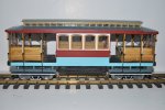
OcCre San Francisco Streetcar Build

3 minutes of fame

3d printing, electronics and trams
14 Dec 2020
574
154
Lincolnshire
www.mgnr.uk
Best answers
0
Country flag
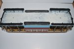
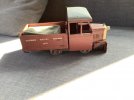
The roof is on, following the OcCre instructions, however the instructions says "apply filer", but there is no hint as to what type of filler, so being a wooded roof, I used a water based wood filler, the one that "does what it says on the tin" :) :
View attachment 297021

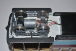
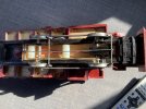
I have also completed the electronics, the components all fitted in small plastic "project box" fixed under the body:

View attachment 297022

So having fitted the bogies and powered the electronics up, this is when the problems started. It would seem that my original motor would not be driven by the Rx, As you can see it is a 3.7 volt battery and a 3 - 6 volt motor but even though every bound the Rx stopped with an error flash. change of motor (same physical size) bu 6 -12 volts, and no problem at all. Put on my test track and the wheels just slip, no traction, the whole item just weights 900 gms, and with two bogies, only one driven that is 450 gms loading. An extra 500 gms over the power bogie and away it goes, but my issue is where 500 gms of additional ballast can be added, with the open design, there are no hiding places - still considering my options.
Superb!
Very neat electronic installation, much better than I ever manage. I used ordinary wood filler and plenty of sanding on the roofs of my tram cars and it's worked and remained very well indeed.

It you are ever in my part of Lincolnshire, I'd only be too happy to grant you running powers over my line :)
 

PhilP

G Scale, 7/8th's, Electronics
5 Jun 2013
33,592
3,525
Nottingham
Best answers
0
Country flag
I have black self adhesive wheel weight strips.. 60g per strip.
Could you cover much of the under-floor with those?

PhilP
 

JimmyB

Now retired - trains and fishing
23 Feb 2018
6,957
923
69
Weston-super-Mare
www.tumble-down-falls.co.uk
Best answers
0
Country flag
I have black self adhesive wheel weight strips.. 60g per strip.
Could you cover much of the under-floor with those?

PhilP
Phil, I will get some more photos, but not much of the underfloor left, the bogies take up much of it and the electronics the rest.
 

Paul M

Registered
25 Oct 2016
11,909
1,698
61
Royston
Best answers
0
Country flag
I have black self adhesive wheel weight strips.. 60g per strip.
Could you cover much of the under-floor with those?

PhilP
No room inside the tram?
 

Rhinochugger

Retired Oik
27 Oct 2009
36,768
4,243
North West Norfolk
Best answers
0
Country flag
The B2B is 41mm isn't it? That might make a difference
Interesting, I measured the B2B of a number of items LGB/Bachmann/Accucraft/IP/Timdon, and none were 41mm all being narrower, ranging from 39.6 to 40.5, however the majority were around 40.2 - 40.3 mm.
From memory, it's around 40.4mm but .........................

I have traditionally used an LGB plastic wheelset and the Mk1 eyeball for gauging wheels. I take the LGB wheelset and place it flange point to flange point with the wheelset that I'm adjusting. This method has never yet failed me ......... insofar as it has never been a cause for derailments.

I am a devout bodger, but the engineers among us may choose to disregard this post :p:p:p:p:p
 

dunnyrail

DOGS, Garden Railways, Steam Trains, Jive Dancing,
Staff member
GSC Moderator
25 Oct 2009
26,206
4,997
75
St.Neots Cambridgeshire UK
Best answers
0
Country flag

JimmyB

Now retired - trains and fishing
23 Feb 2018
6,957
923
69
Weston-super-Mare
www.tumble-down-falls.co.uk
Best answers
0
Country flag
Having determined that the only place for the weight was under the floor, and this would have a knock on effect on the bogie height, I worked out that if I removed the spacers from the top of the bogies (which allow bogies lateral movement), this will give me 6 mm to play with. Having identified some "hard lead shot" at approximately 3 mm diameter that would give two layers of shot. I also decided that I would apply the weight across the whole underfloor which would hopefully hold the none-powered bogie to the track. So 1 kg og shot was ordered, and after hopefully sealing any crevice where resin could escape I added the shot, and the 1 kg was a perfect fit, and 2-part polyurethane resin was used to pot the weight:

DSC_0029.JPG

However, as usual there was some seepage, so some light cleaning to the resin, and removal of any unwanted resin:

DSC_0032.JPG

Because I had removed the spacers from the bogies, on initial test it did not run well due to lack of lateral movement, however bevelling on the bogie surface allowed sufficient bogie movement, so it now runs, however the motor I am using which I thought was 9 volts is not sufficient to drive up any gradient, and is very slow, so I have a new motor on order.

Motorization Conclusion:

The weight of this model has now tripled, and has traction, if you are considering motorizing one of these add weight early, there are 6 seats that could take a reasonable amount of weight, and the weight under the floor helps, but all this would be best considered before roof assembly.
 

JimmyB

Now retired - trains and fishing
23 Feb 2018
6,957
923
69
Weston-super-Mare
www.tumble-down-falls.co.uk
Best answers
0
Country flag
With thanks to DafyddElvy DafyddElvy in his Tram Weight to Gradient Ratio thread, and comments from Greg Elmassian Greg Elmassian in his post Tram Weight to Gradient Ratio I have realised what the issue may with some lack of traction. To recap, no additional weight, and no traction at all; 1kg of weight and I now have traction on the flat, however I am loosing traction on gradient. I had already thought about both axles on the power bogie being driven but not sure how to achieve this due to the lack of room on the bogie, though I think it could be the best option. Greg mentioned "sprung" axles, my assumption is this is what some of us call compensating, because when I now think about it 4 wheels close together, one is bound not to touch the track if they are in a fixed position, so is the none powered axle can "rock" then all four wheels will touch the track. I am going to carry out a short trial with the none powered axle removed, so the powered axle has full contact, and this may answer some of my questions. I will get back to you.
 

dunnyrail

DOGS, Garden Railways, Steam Trains, Jive Dancing,
Staff member
GSC Moderator
25 Oct 2009
26,206
4,997
75
St.Neots Cambridgeshire UK
Best answers
0
Country flag
With thanks to DafyddElvy DafyddElvy in his Tram Weight to Gradient Ratio thread, and comments from Greg Elmassian Greg Elmassian in his post Tram Weight to Gradient Ratio I have realised what the issue may with some lack of traction. To recap, no additional weight, and no traction at all; 1kg of weight and I now have traction on the flat, however I am loosing traction on gradient. I had already thought about both axles on the power bogie being driven but not sure how to achieve this due to the lack of room on the bogie, though I think it could be the best option. Greg mentioned "sprung" axles, my assumption is this is what some of us call compensating, because when I now think about it 4 wheels close together, one is bound not to touch the track if they are in a fixed position, so is the none powered axle can "rock" then all four wheels will touch the track. I am going to carry out a short trial with the none powered axle removed, so the powered axle has full contact, and this may answer some of my questions. I will get back to you.
Jimmy, have you looked at Delrin Gears Drive? I have used it a lot, bit fiddly but works very well. Essell but others do it also.
 

JimmyB

Now retired - trains and fishing
23 Feb 2018
6,957
923
69
Weston-super-Mare
www.tumble-down-falls.co.uk
Best answers
0
Country flag
So run with the single powered axle, and it seems to work.

Jimmy, have you looked at Delrin Gears Drive? I have used it a lot, bit fiddly but works very well. Essell but others do it also.

Jon, as mentioned in my previous post either both driven axles or compensation, however if you look at the photo below, the room on the bogie is very limited, my thoughts are to add Delrin drive, but I will have to fabricate a new bogie, and rethink, especially the IP engineering 30mm (45mm gauge) wheels as the locking collars take so much room.

DSC_0033.JPG
 

Rhinochugger

Retired Oik
27 Oct 2009
36,768
4,243
North West Norfolk
Best answers
0
Country flag
With thanks to DafyddElvy DafyddElvy in his Tram Weight to Gradient Ratio thread, and comments from Greg Elmassian Greg Elmassian in his post Tram Weight to Gradient Ratio I have realised what the issue may with some lack of traction. To recap, no additional weight, and no traction at all; 1kg of weight and I now have traction on the flat, however I am loosing traction on gradient. I had already thought about both axles on the power bogie being driven but not sure how to achieve this due to the lack of room on the bogie, though I think it could be the best option. Greg mentioned "sprung" axles, my assumption is this is what some of us call compensating, because when I now think about it 4 wheels close together, one is bound not to touch the track if they are in a fixed position, so is the none powered axle can "rock" then all four wheels will touch the track. I am going to carry out a short trial with the none powered axle removed, so the powered axle has full contact, and this may answer some of my questions. I will get back to you.
This is always an issue with scratch-built mechanisms, and with many small volume manufacturers.

The larger volume manufacturers manage to introduce sufficient tolerance / play / wobble - call it what you like) which accommodates the very minor track irregularities.

As usual, we scratchbuilders suffer for our art, and have to go that little bit further.

As you suggest, a bit of rocking motion on the non-driving axle should ensure that both drive axles are on the track all the time and thus delivering maximum traction
 

dunnyrail

DOGS, Garden Railways, Steam Trains, Jive Dancing,
Staff member
GSC Moderator
25 Oct 2009
26,206
4,997
75
St.Neots Cambridgeshire UK
Best answers
0
Country flag
So run with the single powered axle, and it seems to work.


Jon, as mentioned in my previous post either both driven axles or compensation, however if you look at the photo below, the room on the bogie is very limited, my thoughts are to add Delrin drive, but I will have to fabricate a new bogie, and rethink, especially the IP engineering 30mm (45mm gauge) wheels as the locking collars take so much room.

View attachment 297318
Hm yes certainly a case where the inside frames are not working for you. I imagine you will have lopped of the axle ends thus not leaving you the option of outside bearings. Certainly metal inside bearings would give you the space for Delrin Drive, possibly with drilled then cut out slots so that the axles can be dropped in place then secured with small tube soldered to the frames and wire to keep the axles in place. I have used this method over many years on 0 gauge mechs and it works nicely.
 

JimmyB

Now retired - trains and fishing
23 Feb 2018
6,957
923
69
Weston-super-Mare
www.tumble-down-falls.co.uk
Best answers
0
Country flag
Hm yes certainly a case where the inside frames are not working for you. I imagine you will have lopped of the axle ends thus not leaving you the option of outside bearings. Certainly metal inside bearings would give you the space for Delrin Drive, possibly with drilled then cut out slots so that the axles can be dropped in place then secured with small tube soldered to the frames and wire to keep the axles in place. I have used this method over many years on 0 gauge mechs and it works nicely.
I am now looking to build new bogies from plasicard, cast some new outer frames, new rod has been ordered for the axles, and I may change the wheels. Now understanding what has gone wrong and why, I feel I am in far better position to come up with a solution that will remedy the situation :)
 

dunnyrail

DOGS, Garden Railways, Steam Trains, Jive Dancing,
Staff member
GSC Moderator
25 Oct 2009
26,206
4,997
75
St.Neots Cambridgeshire UK
Best answers
0
Country flag
I am now looking to build new bogies from plasicard, cast some new outer frames, new rod has been ordered for the axles, and I may change the wheels. Now understanding what has gone wrong and why, I feel I am in far better position to come up with a solution that will remedy the situation :)
Plasticard will work fine, a friend of mine used plywood and with brass bearings that stood the test of time. Not this example though. Though just looking at the one I have he used some metal rod also. Note how he has made space in the wood side-frames for the bosses to turn. I think this one would suffer fitting of a Delrin drive as well, but as it has rods no issues.
52749165-82B0-4647-B4E1-4E554253D46C.jpeg
Someone bound to ask what it is.
F1B6DAFF-FF35-4974-90F1-79A33E47F634.jpeg
 

JimmyB

Now retired - trains and fishing
23 Feb 2018
6,957
923
69
Weston-super-Mare
www.tumble-down-falls.co.uk
Best answers
0
Country flag
To overcome my issues and understand my traction problems I started a thread on Bogie Construction, which provided lots of ideas guidance and advice, with the two main potential issues to traction being Sprung Compensations on the axles and Drive to both wheels. To enable these I decided to build a bogie chassis with inside frame, which would later have dummy bogie outer frames.
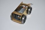
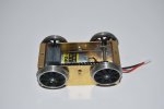
The bogie frame made with 0.080" brass sheet, commercial frame spacers, and Horn Bl;ocks with Sprung Compensation, and Delrin chain drive. It has taken some time due to domestic duties, and waiting for parts, but I assembled it yesterday, and the bogie ran, so temporally attaching the Streetcar I gave it a run including my 1:24 gradient, and there was NO wheel slip. Of course other issues that I suspected would manifest themselves, did, but these were poor judgement calls on my part and are easy fixes, the good point is it worked:

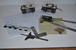
The original bogies that I wish to emulate in looks, and a rough drawing:

DSC_0034.JPG

The assembled bogie showing the gearbox and drive, the compensated horn blocks just visible at the back

DSC_0035.JPG

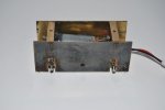
A view from underneath showing the compensation and my messy (but effective) soldering:

DSC_0036.JPG

Wheels removed to chemically blacked the frames to make them less visible through the dummy frames

DSC_0037.JPG

The dummy frames are almost complete however due to the bogie pivot being behind the motor, I am in the process of devising an assemble method which will allow easy(ish) disassembly.
 

Rhinochugger

Retired Oik
27 Oct 2009
36,768
4,243
North West Norfolk
Best answers
0
Country flag
To overcome my issues and understand my traction problems I started a thread on Bogie Construction, which provided lots of ideas guidance and advice, with the two main potential issues to traction being Sprung Compensations on the axles and Drive to both wheels. To enable these I decided to build a bogie chassis with inside frame, which would later have dummy bogie outer frames.
The bogie frame made with 0.080" brass sheet, commercial frame spacers, and Horn Bl;ocks with Sprung Compensation, and Delrin chain drive. It has taken some time due to domestic duties, and waiting for parts, but I assembled it yesterday, and the bogie ran, so temporally attaching the Streetcar I gave it a run including my 1:24 gradient, and there was NO wheel slip. Of course other issues that I suspected would manifest themselves, did, but these were poor judgement calls on my part and are easy fixes, the good point is it worked:

The original bogies that I wish to emulate in looks, and a rough drawing:

View attachment 298950

The assembled bogie showing the gearbox and drive, the compensated horn blocks just visible at the back

View attachment 298951

A view from underneath showing the compensation and my messy (but effective) soldering:

View attachment 298952

Wheels removed to chemically blacked the frames to make them less visible through the dummy frames

View attachment 298953

The dummy frames are almost complete however due to the bogie pivot being behind the motor, I am in the process of devising an assemble method which will allow easy(ish) disassembly.
Brass is difficult to solder because it dissipates heat too quickly - so thick brass is even more difficult to solder :emo::emo: