collectors
Registered
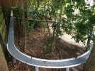
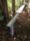
Shall we say i broke ground with the start of this venture. & got my 1st 6 of 80 supports in today. I am building this layout with scaffold & composite decking as it seemed robust & cost effective for the size. We are looking at around 80met of twin track with RC battery trains & wi-fi controlling the rest. I will update this post as i proceed. The photos are the plan, start of the poles & the garden. "Up to the oak on the right" The poles will be a lot shorter.


 So far they feel really solid. The postcrete i am using is perfect for the job, but be warned & be prepared as you only get 5 minutes to work with postcrete before it becomes unworkable & its solid in ten. But a great product to use & not have to mix it. Saves your back.


")
")